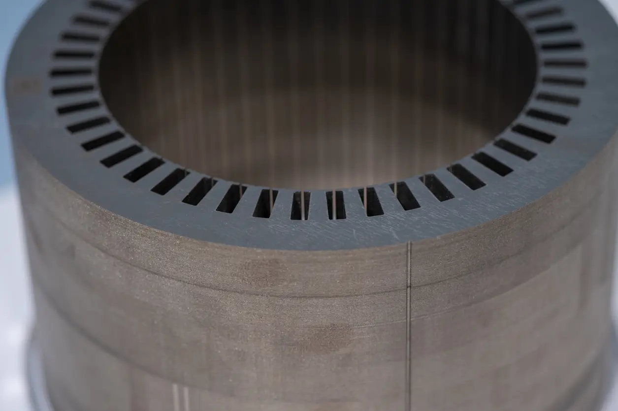
Stacking factor is the fraction of a laminated stack that is actually steel. Standards set minimums by thickness: IEC 60404-8-8 requires at least 0.92 for uncoated 0.15 mm non-oriented strip and 0.95 at 0.35 mm, and IEC 60404-8-4 lists 0.96 at 0.50 mm. Those values come from flat, deburred test strips compressed under a defined pressure. A stamped and joined motor core is a different object, so its stacking factor needs its own definition and its own check.
This matters most when one number is carried from a mill datasheet into FEA, then onto a drawing, and finally into an incoming inspection. Each of those steps can quietly mean something different by “stacking factor.”
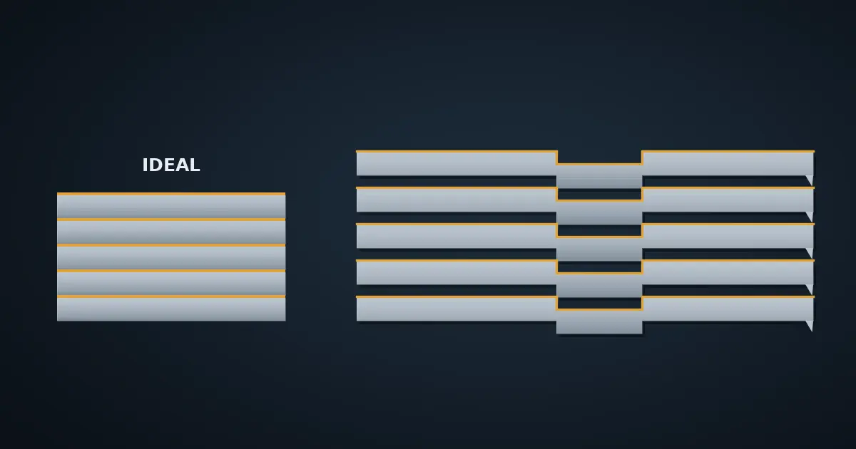
What is stacking factor in electrical steel?
ASTM A719/A719M defines lamination factor (also called space factor or stacking factor) as the ratio of an equivalent solid volume, calculated from specimen mass and true density, to the measured volume of a compressed strip stack. In height terms:
- Stacking factor = steel height ÷ total stack height, equivalently
- SF = m ÷ (ρ × A × H), where m is stack mass, ρ the steel density, A the lamination area, and H the measured stack height under the specified pressure.
ASTM states that the factor reflects the “deficiency of effective steel volume” caused by oxides, roughness, insulating coatings and other surface conditions. The international method is IEC 60404-13, which covers resistivity, density and stacking factor for grain-oriented and non-oriented strip and sheet, measured at (23 ± 5) °C.
Two details from these methods matter later. ASTM A719 recommends a minimum test pressure of 50 psi (345 kPa), so stack height is always a pressure-dependent quantity. And IEC 60404-8-8 requires the stacking-factor test strips to be “carefully deburred before the test.”
What stacking factor do the standards and datasheets specify?
The table below collects specified minimums across the 0.15 to 0.50 mm range Yucore Technologies works in, plus two mill datasheets that show the gap between guaranteed and typical values.
| Source | Thickness (mm) | Stacking factor | Basis / condition |
|---|---|---|---|
| IEC 60404-8-8 (2017+AMD1:2026), Table 1 | 0.15 | 0.92 min | Non-oriented, uncoated test specimens |
| IEC 60404-8-8, Table 1 | 0.20 | 0.93 min | Non-oriented, uncoated test specimens |
| IEC 60404-8-8, Table 1 | 0.25 / 0.30 | 0.94 min | Non-oriented, uncoated test specimens |
| IEC 60404-8-8, Table 1 | 0.35 | 0.95 min | Non-oriented, uncoated test specimens |
| IEC 60404-8-4 (2022+AMD1:2026), Table 1 | 0.35 / 0.50 | 0.95 / 0.96 min | Fully processed non-oriented; coated-product stacking factor is by agreement |
| JFE Steel catalog, 20JNEH1200 / 20JNEH1500 | 0.20 | 93.0% min; 97.0% typical | Typical value measured with A coating per JIS C 2550-5; “not for guarantee” |
| JFE Steel catalog, 25JNE1350 | 0.25 | 94.0% min; 98.0% typical | Same basis as above |
| Nippon Steel catalog, thin-gauge HX series (15HX1000, 20HX1300, 25HX/27HX) | 0.15 / 0.20 / 0.25 / 0.27 | Min: ≥90.0 / ≥93.0 / ≥94.0 / ≥94.5%. Typical: 96.0 / 97.0 / 98.0 / 98.0% | Tested per JIS C 2550:2000; typical values are not guaranteed |
| Nippon Steel catalog, HX series (35HX, 50HX) | 0.35 / 0.50 | Min: ≥95.0 / ≥96.0%. Typical: 98.0 / 98.5% | Same basis as above |
| China Steel (CSC) 2026 specification, coating table | Not stated in table | ≥97.5% (C6N8, regular 0.4 to 0.8 µm); ≥96.5% (C3S self-bonding, regular 1.0 to 2.0 µm) | Minimum by coating type and coating-thickness class |
Three patterns stand out. Both the specified minimum and the typical value fall as the sheet gets thinner. In Nippon Steel’s HX series, the typical value drops from 98.5% at 0.50 mm to 96.0% at 0.15 mm, because coating, oxide and surface roughness occupy a larger share of each layer. Guaranteed and typical values can differ by several points for the same grade. And thicker or bonding-type coatings lower the coating-related minimum.
Why is the datasheet stacking factor not the stacking factor of your core?
The standard number is a property of the steel under a defined test. The core number is a property of the part. ASTM A719 makes this explicit: the term lamination factor “pertains strictly” to its own sampling and procedure, and alternative usages fall outside the method.
| Factor | Standard test specimen | Production motor core |
|---|---|---|
| Geometry | Straight strips of controlled width and length | Full lamination with slots, teeth, bore and pockets |
| Edges | Carefully deburred before the test (IEC 60404-8-8) | As cut or stamped, with the burr the process leaves |
| Compression | Defined pressure (ASTM recommends ≥345 kPa) | Whatever the joining method, fixture or housing applies |
| Joining | None | Interlocking, welding or bonding, each with its own effect on height and contact |
| Coating | Stated coating, or uncoated for the IEC 60404-8-8 minimums | Ordered coating, plus any bonding layer |
Joining also changes more than height. A study of interlocked CoFe stator stacks from TU Darmstadt and VACUUMSCHMELZE notes that interlocking can create local electrical contact between sheets, causing additional eddy currents, and that embossing and stacking pre-stress affect material properties much like cutting does. Stacking factor does not capture any of that. A core can meet its stacking-factor target and still lose more than the model predicts.
How should stacking factor be used in FEA?
Most electromagnetic tools treat stacking factor as a homogenization input, not a geometry change. Ansys Maxwell documentation is a useful example:
- With a stacking factor below 1, the plotted flux density is the average across steel and gaps, not the flux density inside the steel.
- Core-loss coefficients need rescaling when stacking factor is used: Kh/SF, Kc/SF and Ke/√SF.
The practical sensitivity is easy to show with the JFE 0.20 mm example above. If a model uses the 97.0% typical value and the delivered core sits at the 93.0% guaranteed minimum, the steel cross-section is 0.93 ÷ 0.97 ≈ 0.959 of what was modeled. That is about 4% less steel, and the flux density inside the steel rises by about 4% (0.97 ÷ 0.93 ≈ 1.043) for the same flux. Near the knee of the B-H curve, that shift is not small.
This is the same discipline described in our article on AI surrogate FEA verification: control the steel grade, thickness, coating, stacking factor and joining assumptions together, and revisit outputs when any of them change. The checklist in AI-optimized motor design makes the same point for stacking and joining effects.
How do you check stacking factor on a finished core?
A mass-based estimate is the most practical check on a built stack:
- Weigh the stack, with any non-steel parts removed or accounted for.
- Take the lamination area A from the released CAD of the lamination.
- Measure stack height H at an agreed clamping condition and at agreed locations.
- Use the density the steel supplier states for the grade (IEC tables give conventional densities such as 7.60 or 7.65 kg/dm³).
- Calculate SF = m ÷ (ρ × A × H) and record the clamping condition with the result.
This is not an ASTM A719 or IEC 60404-13 result, and it should not be reported as one. It is a part-level number. Its value comes from being measured the same way every time, on the process that will actually ship.
How should stacking factor be specified on a drawing or RFQ?
Yucore insight: a stacking-factor line on a drawing is only as useful as its definition. “Stacking factor ≥ 0.95” does not say whether it means the steel’s IEC minimum, a mill typical value, or the built core. Our recommendation is to make the drawing answer five questions:
| Question | Why it matters |
|---|---|
| Is the requirement on the steel or on the core? | The steel value is a mill certificate item; the core value is a part inspection item. |
| Which method and pressure? | Height, and therefore stacking factor, depends on clamping condition. |
| Which grade, thickness and coating? | Minimums move with thickness and coating class (see the table above). |
| Is the stack controlled to height or to lamination count? | The two cannot both be fixed; one becomes the result of the other. |
| Which joining method? | Interlocking, welding and bonding each change height, contact and stress differently. |
Process stage matters too. Yucore’s own process ladder runs from wire EDM for prototype and very-low-quantity cores, to simple-die stamping for low-volume production, to progressive-die stamping at scale. Edge condition and joining can change at each step, so we treat stacking factor as a value to re-measure at each step, not one to carry forward from the prototype.
Stacking factor is one of several core-construction choices covered in our electric motor stator guide. For how lamination thickness and insulation control eddy-current loss, see laminated stator core design and the rotor lamination guide.
What is a typical stacking factor for motor laminations?
Mill typical values for coated non-oriented steel run from about 96% at 0.15 mm to about 98.5% at 0.50 mm, and they fall as the gauge gets thinner. Nippon Steel’s HX series lists 96.0% at 0.15 mm, 97.0% at 0.20 mm, 98.0% at 0.25 to 0.35 mm and 98.5% at 0.50 mm (JIS C 2550, not guaranteed). Guaranteed minimums are lower, from 90 to 92% at 0.15 mm up to 96% at 0.50 mm. A stamped and joined core can differ from either figure, so measure or agree on the built-core value instead of assuming it.
Is stacking factor the same as lamination factor or space factor?
Yes. ASTM A719/A719M states that lamination factor is also termed space factor or stacking factor. IEC 60404 documents use “stacking factor.”
Does a thinner lamination always have a lower stacking factor?
Generally yes, but not always. Typical values fall as gauge gets thinner, from 98.5% at 0.50 mm to 96.0% at 0.15 mm in Nippon Steel’s HX series, and specified minimums follow the same pattern: IEC 60404-8-8 lists 0.92 at 0.15 mm and 0.95 at 0.35 mm for uncoated non-oriented strip. Actual values depend on coating, flatness and edge condition, so compare grades on the same basis.
Should FEA use the minimum or the typical stacking factor?
Use the value the delivered core can be held to. Mill typical values are stated as not guaranteed (JFE and CSC both say so), so a guaranteed minimum or a measured value from a comparable built core is safer, with a sensitivity run across the expected range.
Does stacking factor affect core loss?
Yes, indirectly. A lower stacking factor raises flux density inside the steel for the same flux, and tools such as Ansys Maxwell require loss coefficients to be rescaled when it is applied. Losses from interlaminar contact at joints or burrs are separate and are not captured by stacking factor.
Does a self-bonding coating lower stacking factor?
The coating itself takes up height. CSC lists ≥96.5% for its regular C3S self-bonding coating (1.0 to 2.0 µm) versus ≥97.5% for its regular C6N8 coating (0.4 to 0.8 µm). Whether the finished core is better or worse overall depends on what the bonding replaces, such as interlocks or welds.
Can stacking factor be measured on a finished stator?
It can be estimated from mass, lamination area, density and stack height under a stated clamping condition. That is a part-level value, not an ASTM A719 or IEC 60404-13 result, so the method should be agreed with the supplier.
Sources
- IEC 60404-13:2018, Methods of measurement of resistivity, density and stacking factor of electrical steel strip and sheet. IEC webstore
- IEC 60404-8-8:2017+AMD1:2026, Thin electrical steel strip and sheet for use at medium frequencies (Table 1, 7.3.2, 8.3.3.1). IEC webstore
- IEC 60404-8-4:2022+AMD1:2026, Cold-rolled non-oriented electrical steel strip and sheet, fully processed (Table 1, 6.3). IEC webstore
- ASTM A719/A719M-14(2019), Standard Test Method for Lamination Factor of Magnetic Materials. ASTM
- JFE Steel, Electrical Steel Sheets catalog (JNE thin-gauge tables). PDF
- Nippon Steel, Electrical Steel Sheets catalog (D003jec), HX and HXS series specification and typical-property tables; lamination factor per JIS C 2550:2000.
- China Steel Corporation, Electrical Steel product specification (2026), sections 8.1 and 8.4. PDF
- Ansys Maxwell Help, Lamination Modeling. Ansys Help
- D. M. Martin et al., “Design Guidelines for interlocked stator cores made of CoFe sheets,” IOP Conf. Ser.: Mater. Sci. Eng. 1238 (2022) 012036. IOP Science
If you are setting a stacking-factor requirement for a new stator or rotor core, send us the drawing and steel grade and we will review how the definition, joining method and process stage fit together.