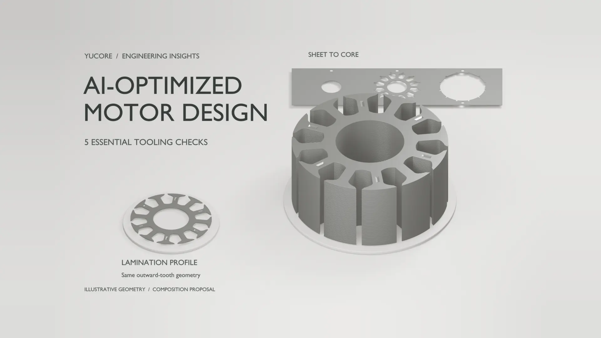
An AI surrogate needs FEA verification when a prediction will determine which motor design advances, whether a constraint is satisfied, or whether tooling can proceed. Recheck shortlisted candidates when local accuracy is uncertain, performance margins are narrow, or geometry and manufacturing assumptions have changed. Held-out data assesses predictive accuracy, while a fresh finite element analysis checks the selected candidate against a physics model; neither proves physical motor performance or production feasibility.
This checkpoint connects simulation decisions to From AI-Optimized Motor Design to Manufacturable Motor Cores, before material, tooling, assembly, and production validation.
What does the AI surrogate’s validation actually cover?
A surrogate approximates relationships learned from simulation or experimental data. Define its permitted geometry, materials, operating conditions, and predicted outputs. Accuracy for average torque does not establish accuracy for torque ripple, core loss, or rotor stress.
Review training and validation errors separately. Keep a final test set outside model selection, and prevent data leakage through preprocessing or repeated test-set use. For closely related geometries, assess whether the split tests the intended new designs. Being inside parameter bounds alone does not establish local accuracy; sparse combinations and nonlinear responses can remain poorly represented.
Record the source solver, material data, sampling method, and excluded operating regions. A low test error cannot reveal physics absent from the training labels, or demonstrate accuracy for an operating condition the evaluation never exercised.
When should FEA verification interrupt screening?
Compare credible local prediction error with the candidate’s advantage and its distance from a constraint. The following decision framework separates routine screening from cases where fresh solver evidence could change the choice.
| Candidate condition | Recommended next step |
|---|---|
| Supported region; clear margins | Screen with the surrogate; recheck the shortlist. |
| Sparse coverage or new conditions | Run FEA and reassess the permitted prediction scope. |
| Small ranking gap or constraint margin | Compare fresh FEA results with the baseline and limits. |
| Revised geometry, material, or assembly | Update assumptions and repeat affected checks. |
I would delay a tooling commitment if plausible prediction error could reverse the chosen design’s advantage. A better average test score cannot settle that local decision; acceptable error must follow the output, operating point, and consequence of choosing incorrectly. This is a decision rule, not a universal error threshold.

What does this look like in a motor-design review?
Consider a hypothetical stator review, not a customer case or measured result. Two candidates have similar predicted average torque, but one uses a narrower slot opening and a revised tooth shoe. Tooling review then requires another tooth-shoe adjustment. The surrogate’s original ranking no longer answers which released geometry should advance.
Run the baseline and revised candidate under matched FEA conditions. Compare average torque and the other decision-critical outputs, including cogging torque where relevant, before accepting the tooling trade-off. MERL’s motor-surrogate research describes cogging torque sensitivity to slot openings, tooth-shoe height, and magnet geometry. This example illustrates a verification trigger; it claims no improvement or test outcome.
How should the independent FEA comparison be run?
Evaluate the actual candidate with the physics solver separately from its surrogate prediction. Independent here means a separate solver evaluation, not necessarily another software vendor or external organization. JMAG’s documented optimization workflow includes alternating FEA and surrogate evaluations.
Match geometry revisions, excitation, speed, material curves, temperature assumptions, boundary conditions, and output definitions. Check mesh refinement against the outputs driving the decision, plus time-step or rotor-angle resolution where relevant. Retain assumptions and discrepancies with the results. Solver agreement and mesh convergence do not remove omitted physics or establish agreement with a built motor.
Investigate a disagreement before adding that run to training data; retraining should be followed by renewed validation, not treated as proof that the original decision was sound.
What changes when the core must be manufactured?
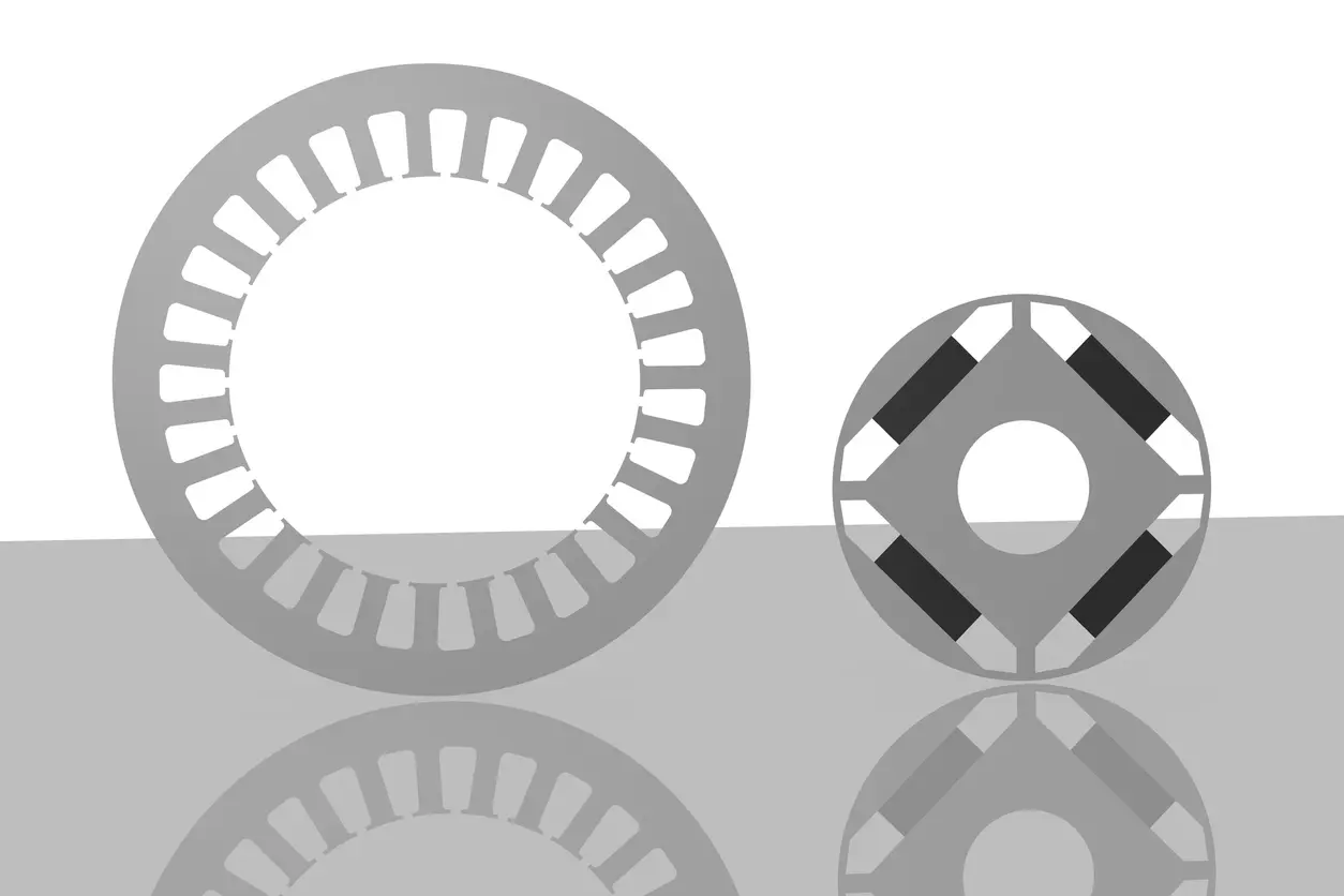
Changes to a slot opening, tooth shoe, or rotor bridge can invalidate earlier comparisons. Control the released drawing, steel grade, thickness, coating, stacking factor, and joining assumptions, then revisit affected electromagnetic, thermal, or mechanical outputs.
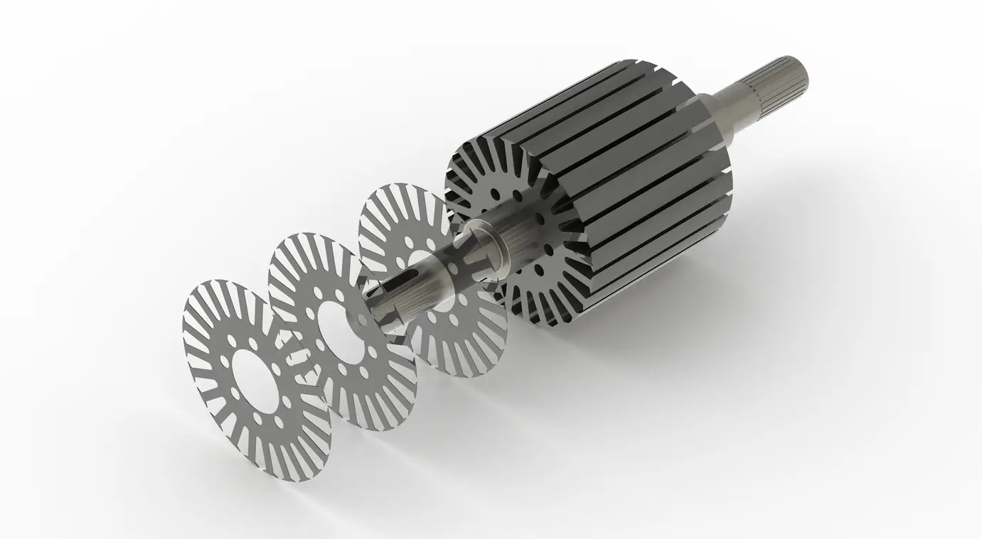
JFE’s motor experiments show that punching and assembly effects depend on material and test conditions. A Wire EDM prototype, simple-die low-volume part, and progressive-die production part therefore need their process assumptions reviewed explicitly. Physical validation uses representative parts and agreed measurements; manufacturing review separately addresses feasible features, tolerances, tooling, and assembly controls.
What should engineers ask before accepting the result?
Does good held-out accuracy remove the need for FEA verification?
No. It supports accuracy over the tested distribution. The selected candidate still needs checks appropriate to its local coverage, margins, and intended use.
What prediction error is acceptable?
There is no universal percentage. Set output-specific tolerances before reviewing the preferred candidate. Use absolute error when relative error becomes misleading near zero.
Does every screened design need a full FEA run?
No. Use a qualified surrogate for screening within its permitted scope. Concentrate fresh solver evaluations on shortlisted, uncertain, changed, or constraint-sensitive candidates.
Does FEA agreement validate the manufactured motor?
No. Physical validation compares predictions with measurements. FEA agreement alone establishes neither built-motor performance nor production feasibility.
For a motor-core manufacturing discussion, contact Yucore Technologies with the controlled drawing, material specification, intended process, and unresolved verification questions.