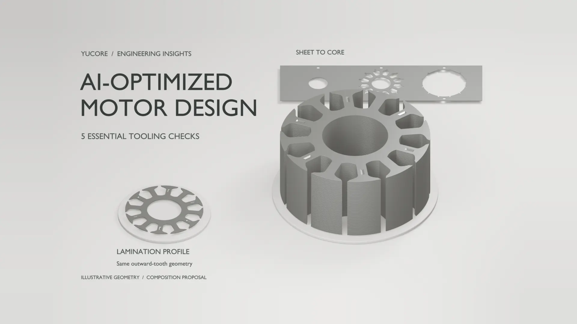
AI-Optimized Motor Design can help engineers explore candidate geometries and competing performance targets. Turning a promising result into a manufacturable motor core requires five checks: independent simulation, matched electrical steel data, producible lamination geometry, realistic stacking and joining assumptions, and production-representative validation. These checks connect the design model to the drawing, tooling route, and physical evidence needed for release. They also give OEM sourcing teams a clearer basis for comparing proposals.
Five checks for AI motor design
1. Verify the candidate independently
Re-evaluate shortlisted candidates with the engineering model used for design sign-off. Check operating points, constraints, mesh sensitivity, and the assumptions behind loss, torque, temperature, and mechanical stress predictions. A surrogate model should not validate its own answer.
JMAG documents optimization workflows that alternate between finite element analysis and surrogate evaluation. A 2026 research preprint similarly found that AI-only search could converge to false optima in its motor-design benchmark. That is simulation evidence, not proof of manufactured performance. The practical lesson is to retain independent physics-based verification, especially when a candidate approaches a constraint or leaves well-supported training data.
Keep the baseline design and candidate results under the same evaluation conditions. If optimization changes the geometry or material assumptions, update the verification model rather than comparing outputs from inconsistent setups.
2. Match the model to the ordered steel
Specify the electrical steel grade, thickness, coating, delivery condition, and relevant magnetic and mechanical data. Compare loss values only at their stated induction and frequency; a catalog value cannot represent every operating point.
Processing condition matters. For example, voestalpine distinguishes fully processed and semi-processed steel. Fully processed steel develops its specified properties at the steelworks, while semi-processed steel requires final annealing after stamping. Confirm the intended treatment with the material supplier. Review rotor strength requirements alongside magnetic performance, then document any substitutions before tooling release. Procurement needs a traceable material specification and approved alternatives, not just a generic request for low-loss steel.
3. Review geometry for the intended tooling
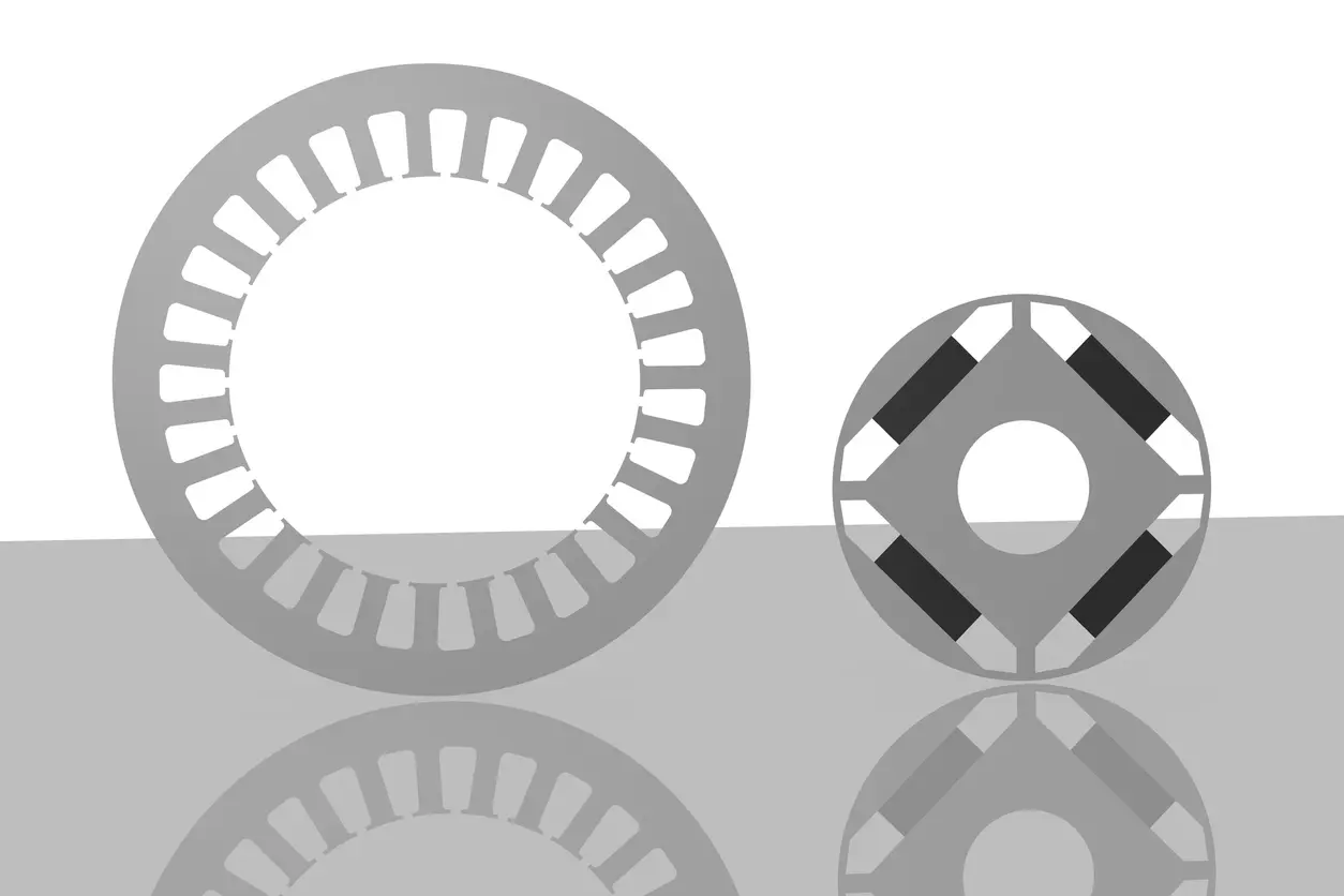
Bring the lamination supplier into the geometry review before freezing the drawing. Examine narrow webs, slot openings, internal radii, magnet pockets, datum strategy, and features needed for handling and stacking. Agree which dimensions are functionally critical and how they will be inspected.
An IPM rotor bridge illustrates the trade-off: a thinner peripheral bridge can reduce magnetic leakage, while mechanical loading and fabrication constrain the acceptable geometry. The rotor bridge design guide explains this balance. Avoid applying a universal minimum web width to every steel and tool. A successful Wire EDM prototype also does not establish that the same geometry is ready for repeatable stamping.
When a tooling review changes a bridge, radius, or pocket, return the revised geometry to electromagnetic and mechanical analysis. Approval should apply to the released geometry, not an earlier optimization image.
4. Include stacking and joining effects
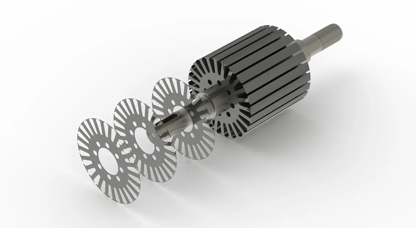
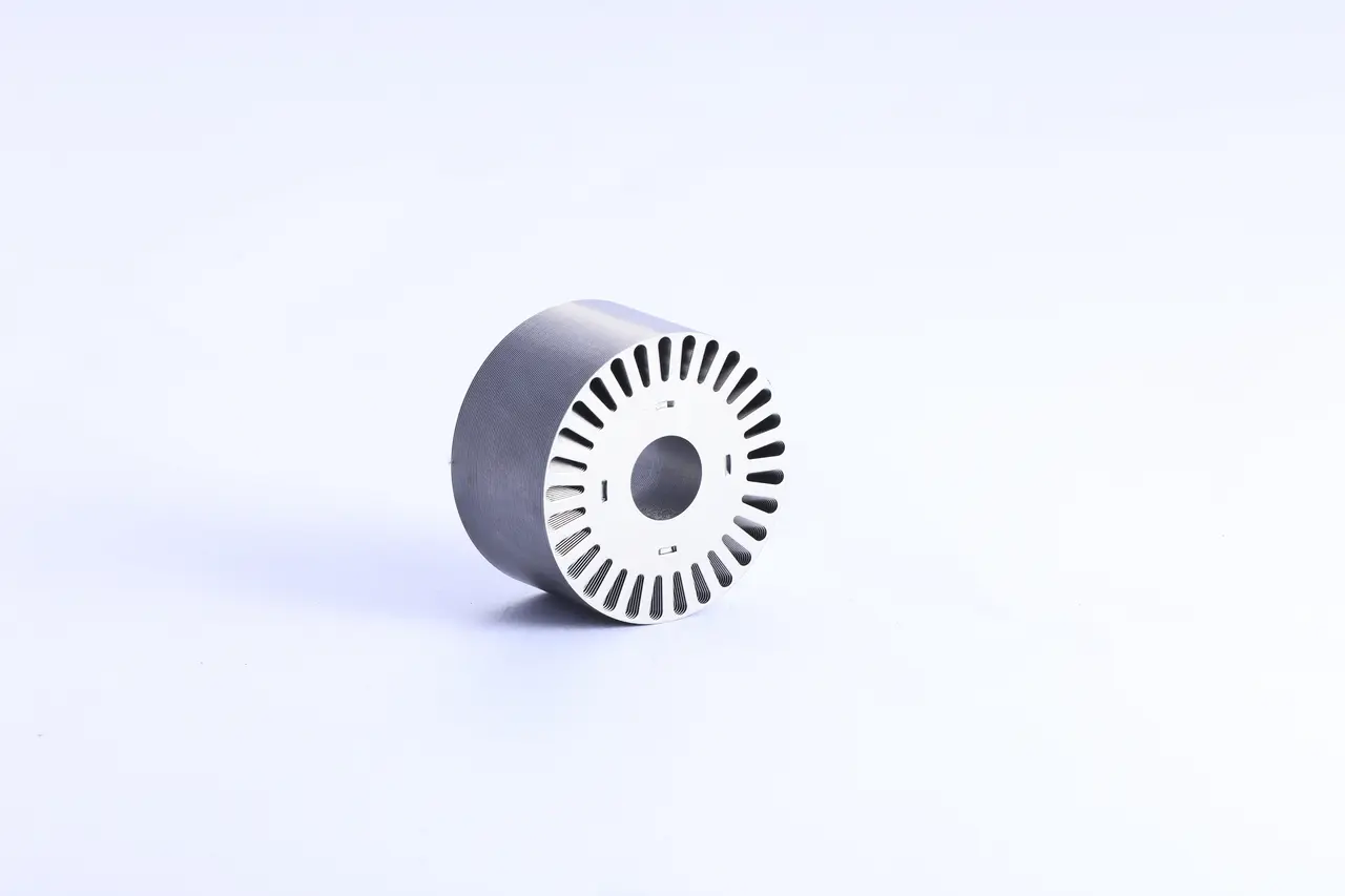
Define how laminations become an assembled core, including the joining method, stack dimensions, alignment requirements, and interfaces with the housing or shaft. Keep these assumptions visible in the design review.
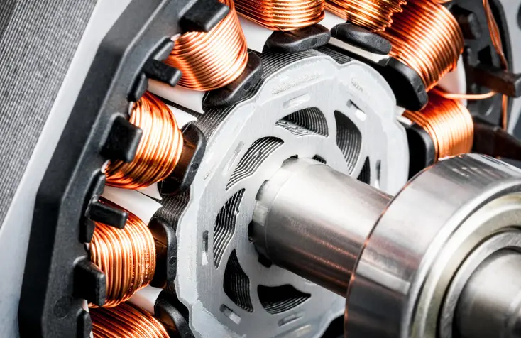
JFE’s ring-core experiments showed that interlock formation, joining strain, and interlaminar electrical paths can affect magnetic properties and losses. The magnitude depends on the tested configuration and conditions. Separate JFE motor experiments also demonstrated material-dependent effects of punching and shrink fitting. Those findings support evaluating the assembled core rather than assuming sheet data transfers unchanged. The rotor lamination guide provides background on why interlaminar insulation matters.
5. Validate the production route before release
Yucore’s manufacturing progression is Wire EDM for prototypes or very low quantities, simple-die stamping for low-volume production, and progressive-die stamping for scale. Select the route against design maturity, quantity, and the evidence needed at the next decision point.
Treat each process transition as a validation decision. Review dimensional results, edge and coating condition, assembled stack geometry, and relevant motor-level performance against agreed acceptance criteria. Where core-loss, thermal, or noise and vibration testing is required, assign responsibility to the OEM, supplier, or an agreed laboratory. Record the tested material and process so a favorable prototype result is not silently carried over to a changed production route.
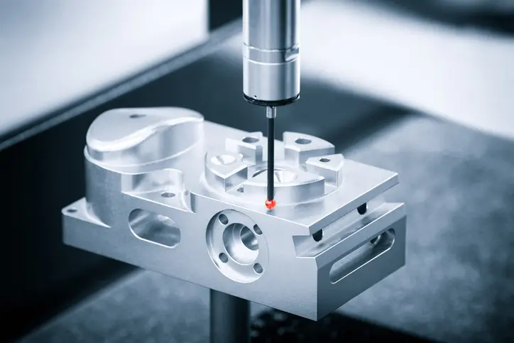
Set the acceptance criteria before samples arrive. A dimensional pass alone does not establish that the complete motor meets its efficiency, durability, or acoustic requirements.
Decision checklist for AI-Optimized Motor Design
Use this checklist to identify missing evidence before committing to the next tooling stage.
| Check | Evidence to retain |
|---|---|
| Independent verification | Rechecked candidates, operating conditions, and constraint results |
| Material match | Approved grade, thickness, coating, condition, and property data |
| Producible geometry | Reviewed drawing, critical features, and inspection plan |
| Stack and joining | Assembly specification and documented performance assumptions |
| Representative validation | Process-traceable results, acceptance criteria, and responsible owners |
The release decision should connect every important model assumption to a controlled specification or a verification result. For engineers and procurement teams, that creates a usable handoff from optimization to manufacturing and a clear record of what still needs to be demonstrated.
Frequently asked questions
Can AI-Optimized Motor Design replace engineering validation?
No. AI-generated candidates still require independent checks of the model, material, geometry, assembly, and relevant physical performance before release.
Does a successful prototype validate progressive-die production?
No. A prototype validates the conditions under which it was made and tested. Changes in cutting, stacking, or joining require a documented review and appropriate additional validation.
When should the lamination supplier review the design?
Before the production drawing is frozen. Early review lets engineers address tooling constraints, critical dimensions, material availability, and inspection requirements while changes remain manageable.
What should an OEM include in the manufacturing handoff?
Provide the controlled drawing, material specification, quantity requirements, assembly requirements, inspection plan, and agreed acceptance criteria, with responsibility assigned for unresolved verification work.