Table of Contents
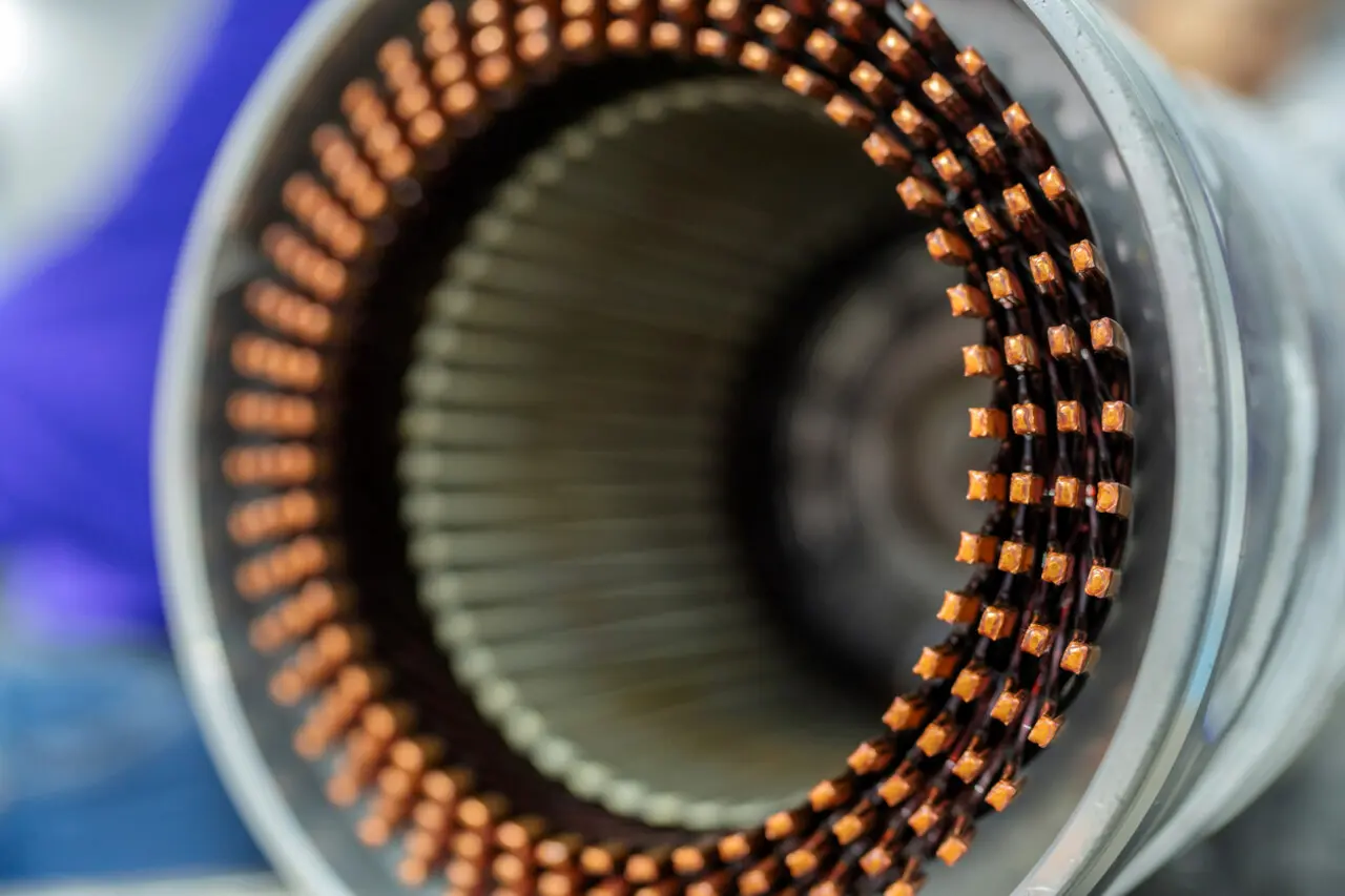
Electric motor design has reached an inflection point where standard, off-the-shelf components increasingly limit innovation. Engineers developing high-performance drives, specialized actuators, or space-constrained applications find themselves constrained by generic lamination stacks that compromise efficiency, form factor, or torque density. Custom motor lamination services offer a pathway beyond these limitations, enabling tailored electromagnetic solutions that align precisely with application requirements.
This guide provides a systematic approach to specifying, sourcing, and implementing custom lamination services. From justifying the engineering investment to delivering precise specifications for manufacturing partners, we’ll examine the critical decisions that separate successful custom implementations from costly mistakes.
Why Settle for Standard? The Engineering Case for Custom Laminations
Standard motor laminations represent a compromise—optimized for broad market appeal rather than specific performance metrics. While adequate for general-purpose applications, they become bottlenecks in designs requiring exceptional power density, unique geometries, or specialized operating characteristics.
Custom lamination services unlock three fundamental advantages: performance optimization through material and geometry selection, complete design flexibility for unique form factors, and the ability to match electromagnetic characteristics precisely to application requirements. These services enable engineers to specify exact slot configurations, optimize flux paths, and select materials based on frequency response, temperature requirements, or magnetic saturation limits.
The decision to pursue custom laminations typically emerges from specific engineering constraints: space limitations requiring non-standard dimensions, efficiency targets demanding optimized core losses, or specialized applications like high-speed spindles or precision servo systems where standard components introduce unacceptable compromises.
Step 1: Justifying the Custom Route
Before engaging custom motor lamination services, engineers must build a compelling technical and economic justification. This analysis should quantify performance gains against additional costs and timeline implications.
Off-the-Shelf vs. Custom Lamination Analysis
| Feature | Off-the-Shelf Laminations | Custom Lamination Services |
|---|---|---|
| Performance | Generic, may not be optimized | Tailored for specific torque, speed & efficiency |
| Design Flexibility | None; locked to standard sizes | Complete freedom for unique shapes & sizes |
| Initial Cost | Low (no tooling) | Can be high (for stamping dies) or (laser, wire-edm) |
| Lead Time | Fast (in-stock) | Varies (days for laser, weeks for stamping) |
| Best Use Case | General purpose, cost-sensitive projects | High-performance, space-constrained designs |
| Example | Standard industrial conveyor motor | High power-density drone motor |
The justification process should include quantitative analysis of performance improvements. For instance, a custom lamination optimized for a specific slot/pole combination might reduce cogging torque by 70% compared to a standard geometry, enabling precise positioning applications. Similarly, material optimization could improve efficiency by 2-3 percentage points in high-frequency switching applications.
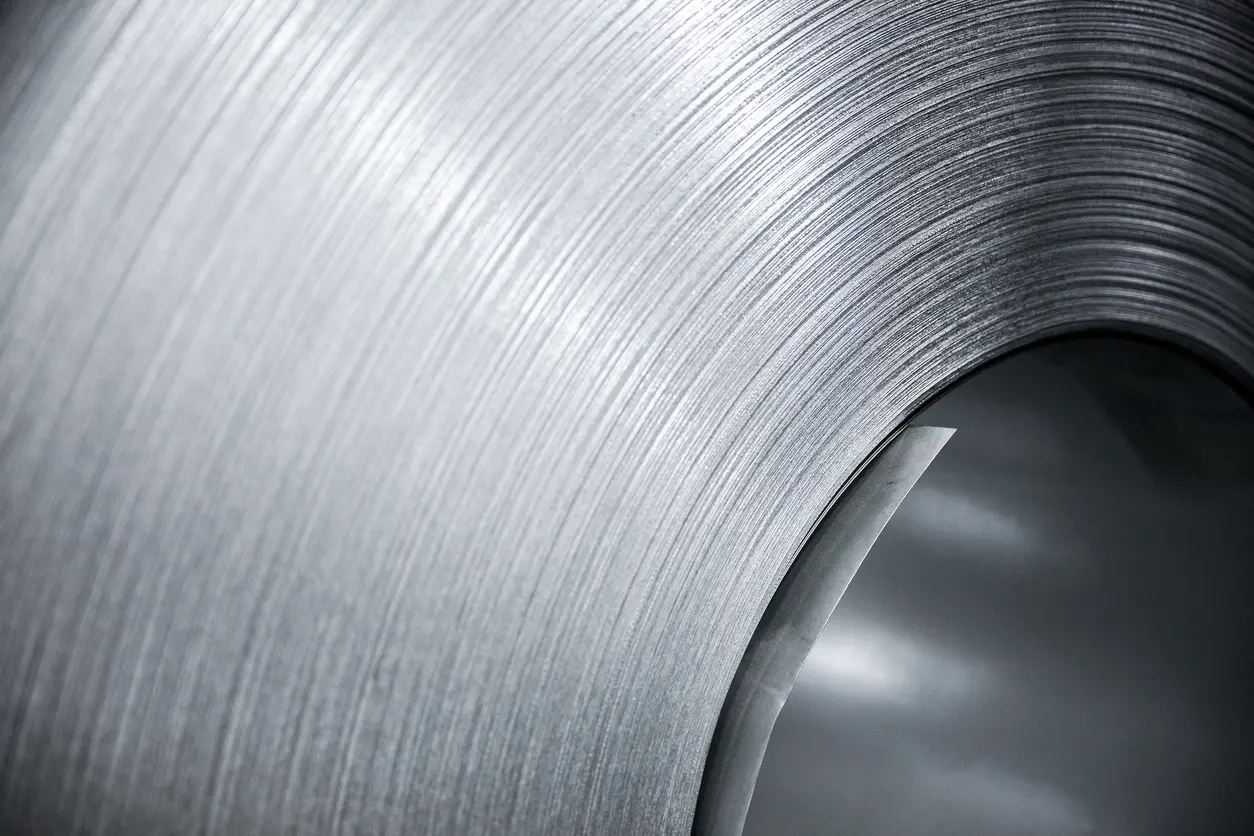
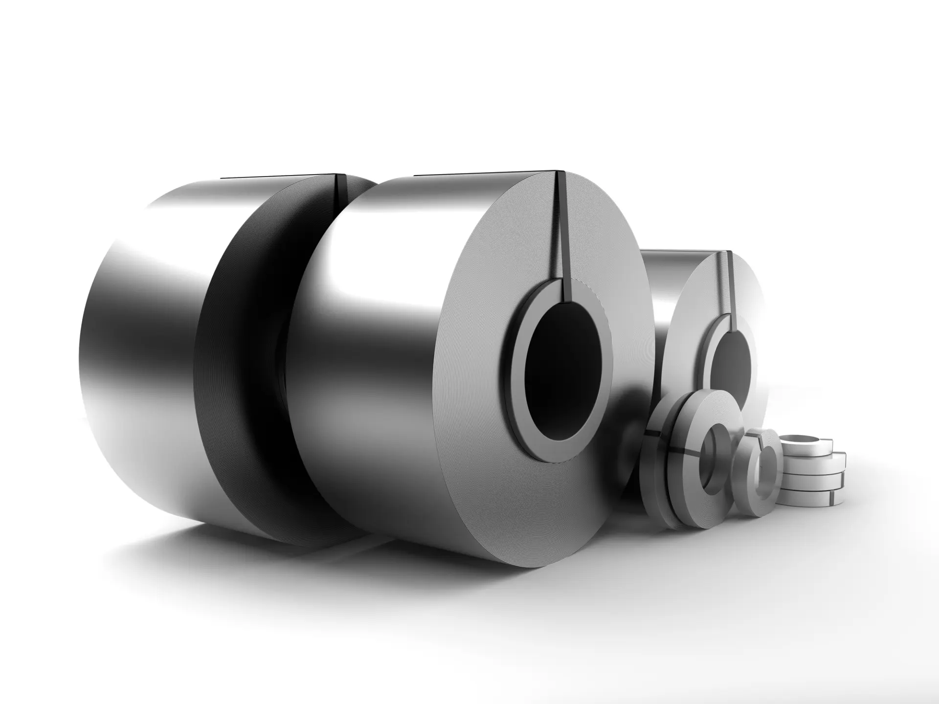
Step 2: Material Selection – The Foundation of Performance
Material selection for custom motor lamination services follows industry standards (ASTM A677, IEC 60404) while addressing specific electromagnetic requirements. The choice directly impacts core loss characteristics, permeability, and achievable power density.
Common Electrical Steel Grades & Applications
| Material Grade | Key Characteristics | Typical Engineering Application |
|---|---|---|
| M19 / M27 | Good permeability, moderate core loss, cost-effective | Industrial motors, transformers, general purpose |
| 20JNEH1200 | Thin gauge, optimized for high frequencies (>400 Hz) | High-speed spindle motors, EV traction motors |
| Cobalt Alloys | High magnetic saturation, excellent thermal stability | Aerospace actuators, military-grade generators |
| Thin Gauge Si-Fe | Very low core loss at high frequencies | Ultra-high efficiency servo motors, medical devices |
Material selection requires matching electrical steel properties to operating conditions. High-frequency applications benefit from thin-gauge silicon steel to minimize eddy current losses, while applications requiring maximum flux density may specify cobalt-enhanced alloys despite higher costs.
The insulation coating selection is equally critical. C-5 organic coatings handle temperatures up to 200°C and provide excellent dielectric properties for most applications. Higher-temperature or high-voltage designs may require C-6 inorganic coatings that withstand up to 800°C but at increased material cost.
Step 3: Aligning Manufacturing Process with Project Goals
Manufacturing process selection represents a fundamental trade-off between tooling costs, per-unit pricing, and production flexibility. Each method offers distinct advantages depending on volume requirements and geometric complexity.
Manufacturing Process Comparison
| Process | Best For… | Tooling Cost | Per-Unit Cost | Key Consideration for Engineers |
|---|---|---|---|---|
| Laser Cutting | Prototyping, R&D, low-volume (1-2,500 units) | None | High | Heat Affected Zone (HAZ) can alter magnetic properties at the edge |
| Progressive Stamping | High-volume production (10,000+ units) | High | Very Low | Burr height must be tightly controlled to prevent shorts |
| Simple-Die | Prototyping, flexible customization | Moderate | Low to Moderate | More labor work and longer turnover time |
| Wire EDM | Ultra-high precision, complex geometries | None | Very High | Slower process, but delivers exceptional accuracy and edge quality |
Wire-EDM and laser cutting provides maximum flexibility for prototype development and low-volume production, with lead times measured in days rather than weeks. However, the thermal cutting process from laser cutting creates a heat-affected zone that can increase core losses near cut edges—a consideration for high-frequency applications.
Progressive stamping becomes economically favorable at higher volumes, typically above 10,000 pieces annually. While tooling costs can exceed $50,000 for complex geometries, per-piece costs drop to fractions of laser-cut and wire-cutting alternatives. Critical quality control focuses on burr height management and dimensional consistency across production runs. For a detailed comparison of laser cutting and stamping processes, visit Laser Cutting vs. Stamping.
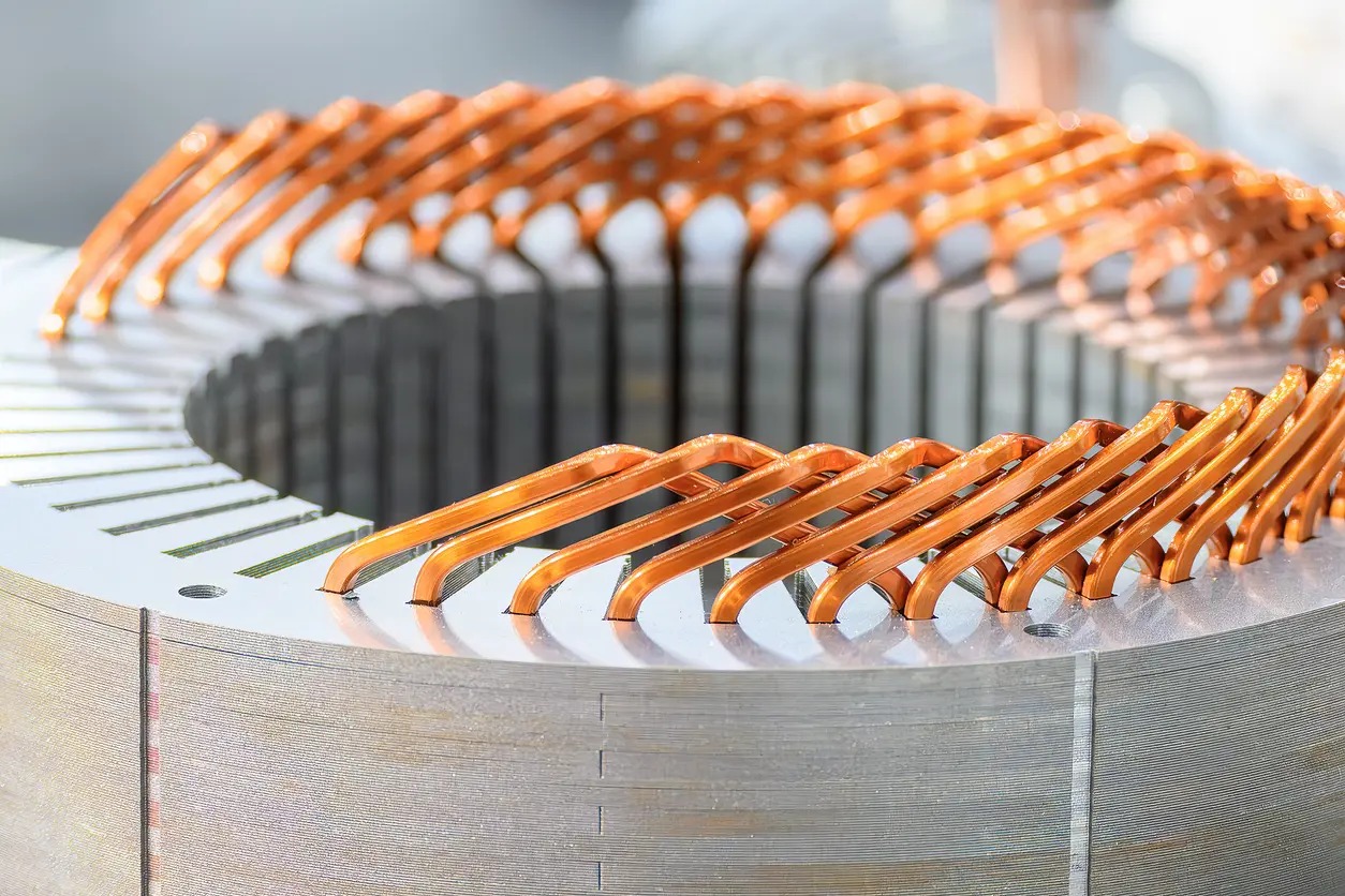
Step 4: Critical Design Specifications for Your RFQ
Precise specification development ensures accurate quotes and functional parts. Incomplete or ambiguous requirements frequently result in costly revisions or performance compromises.
Engineer’s RFQ Checklist
| Specification | Example Value | Why It Matters |
|---|---|---|
| Material Grade & Gauge | M19, 26 Gauge (0.0185″) | Determines magnetic performance and eddy current losses |
| Insulation Coating | C-5 (Organic Enamel) | Prevents shorts between laminations; must withstand winding temps |
| Stack Height & Tolerance | 50mm +/- 0.1mm | Directly impacts motor losses and assembly fit |
| Interlocking Method | Laser Weld or Riveted | Ensures stack integrity under operational stress |
| Burr Height Limit | Max 10 microns | Prevents insulation puncture and electrical shorts |
| Drawing & CAD File | STEP or DXF format | Provides exact geometry for manufacturing |
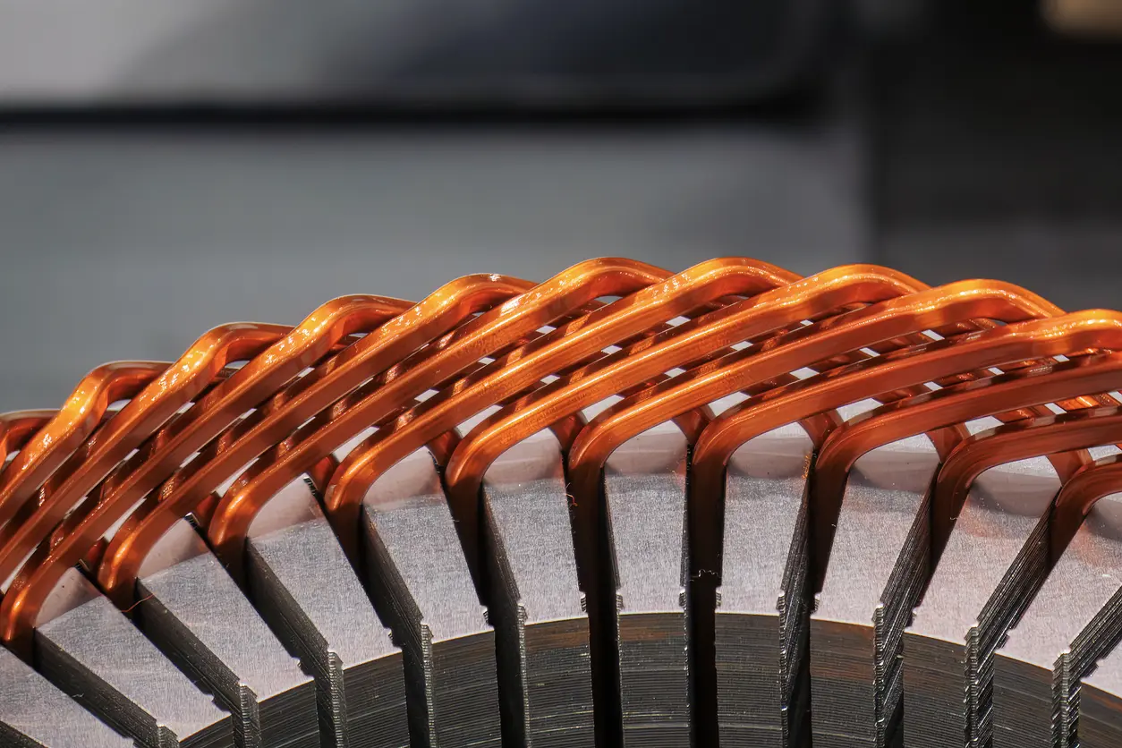
Stack perpendicularity deserves special attention. A stack that deviates from perfect alignment can cause rotor imbalance or prevent proper assembly into housing components. Specify perpendicularity tolerances explicitly—typically within 0.1mm per 50mm of stack height for precision applications.
Quality control requirements should address both dimensional and electrical properties. For high-performance applications, specify core loss testing on sample stacks to verify that manufacturing processes haven’t degraded magnetic properties.
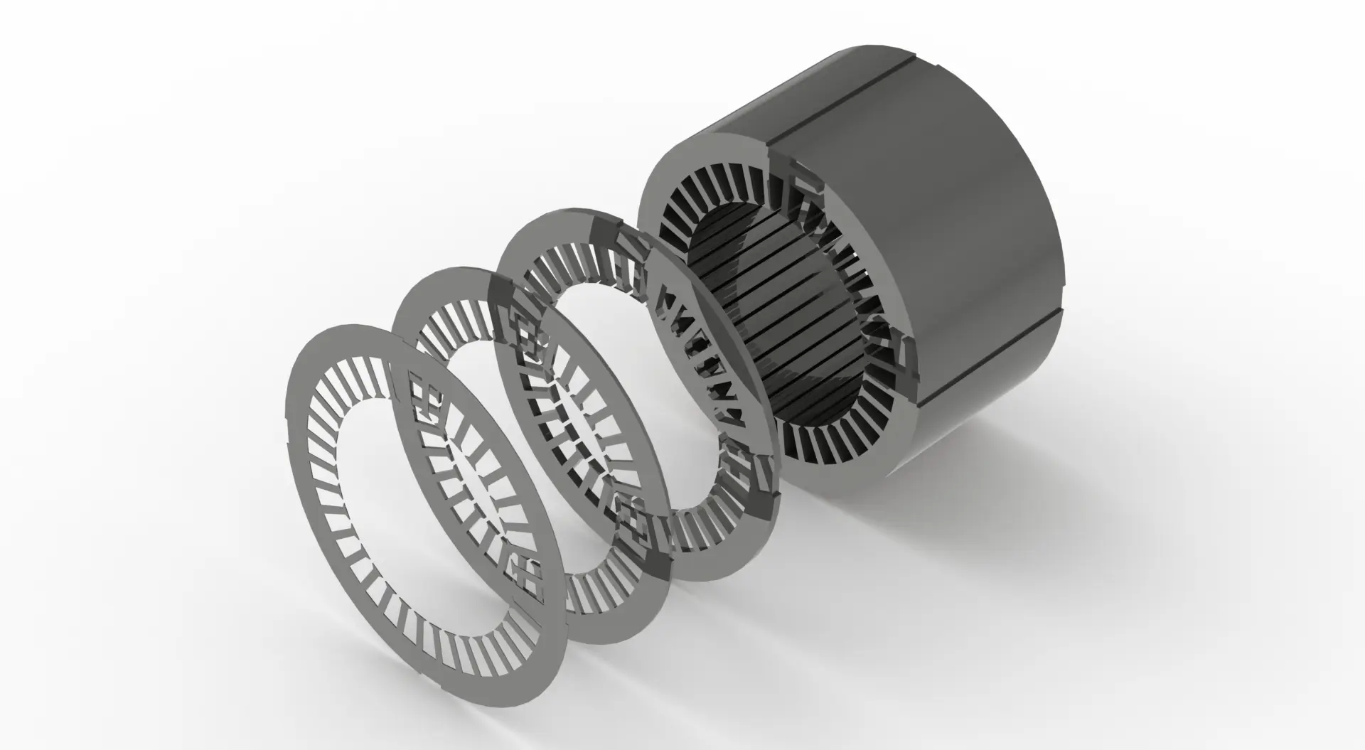
A Motor Designer’s Perspective
“Younger engineers often obsess over lamination geometry but forget the stack itself is a component. I’ve seen beautiful designs fail because the request didn’t specify the stack straightness tolerance. A stack that isn’t perfectly perpendicular can cause rotor imbalance or make press-fitting the stator into its housing impossible and potentially increasing core loss to a higher level. My advice: always include a perpendicularity callout on your stacking drawing; it can save you weeks of assembly headaches.”
This insight highlights a common oversight in custom lamination specifications. While electromagnetic optimization receives significant attention, mechanical integration requirements are equally critical for successful implementation.
Frequently Asked Questions for Engineers
How does lamination thickness affect motor performance?
Thinner laminations reduce eddy current losses, particularly important in high-frequency motors above 400 Hz. This improves efficiency and reduces waste heat generation. However, thinner laminations increase manufacturing cost due to more layers required per stack and potentially more complex handling during assembly.
What is a “C-5” coating and when is it used?
C-5 represents an industry-standard organic enamel insulation applied to electrical steel laminations. It provides excellent dielectric properties and withstands temperatures up to 200°C, making it suitable for most motor applications. Higher-temperature environments above 200°C or high-voltage applications may require C-6 inorganic coating that handles up to 800°C.
What is the ideal way to deliver a design to a service provider?
The optimal specification package includes three components: a 2D PDF drawing with complete tolerances, materials, and manufacturing notes; a 3D CAD file (.STEP format) of the final assembled stack; and a 2D profile (.DXF) of the individual lamination geometry. This combination ensures both manufacturing clarity and design intent communication.
From Specification to Successful Implementation
Custom motor lamination services enable engineers to transcend the limitations of standard components, achieving optimized performance through tailored materials, geometries, and manufacturing processes. Success depends on systematic approach: quantifying the engineering justification, selecting appropriate materials for operating conditions, matching manufacturing methods to volume requirements, and providing comprehensive specifications that eliminate ambiguity.
The engineering investment in custom laminations pays dividends in applications demanding exceptional efficiency, unique field applications, or specialized performance criteria. As motor technology continues advancing toward higher power densities and more demanding operating environments, custom lamination services become increasingly essential tools for innovative design implementation.
Have a challenging motor design requiring custom lamination solutions? Contact our application engineers today to discuss your specific requirements and explore how tailored lamination services can optimize your next project.