Discover how proper stator winding insulation protects your motor’s lifespan and reduces maintenance costs in this essential guide.
Introduction
Stator winding insulation is a critical, yet often overlooked, aspect in both maintenance budgets and capital-equipment specifications. As the main defense against costly failures, stator winding insulation can determine whether an industrial motor runs for two decades or fails within eighteen months. For an in-depth technical review of insulation health monitoring methods and longevity, see this peer-reviewed study on stator insulation state-of-health monitoring. For a broader understanding of how this insulation fits within the overall function of an electric motor stator, see our comprehensive guide.
This unseen barrier—composed of advanced resins, tapes, and varnishes—prevents electrical short circuits, manages thermal stress, and shields copper conductors from corrosive environments. Understanding how stator winding insulation works empowers engineers to predict service life, diagnose early failures, and specify motors that deliver maximum return on investment.
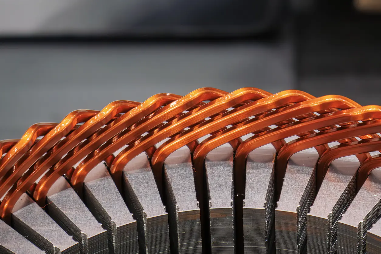
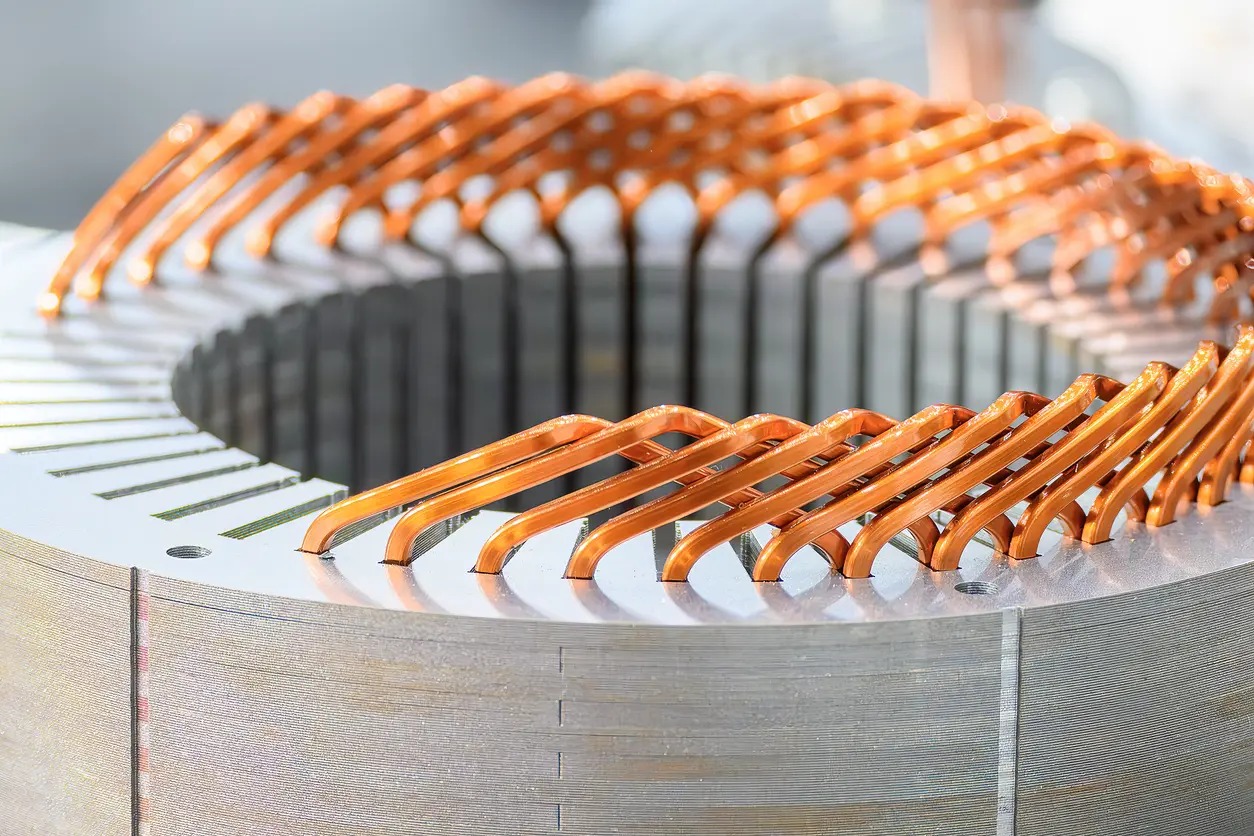
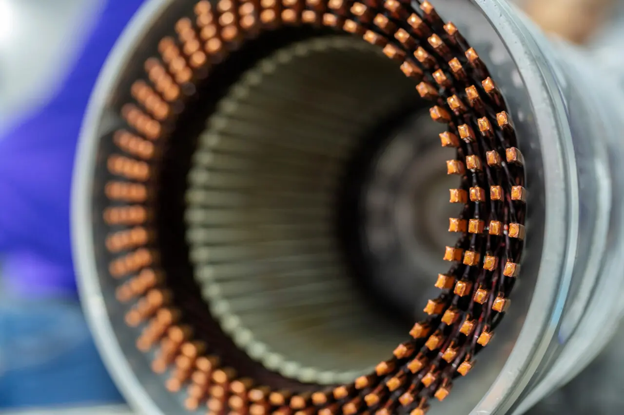
At the very heart of the motor is the stator winding, where electromagnetic fields convert electrical energy into mechanical torque. Stator winding insulation forms the boundaries between adjacent copper turns, phases, and between energized windings and the grounded stator core. When stator winding insulation degrades, current can leak across unintended paths, causing catastrophic short circuits that can destroy a motor in seconds.
This post examines the four protective functions of stator winding insulation, compares insulation classes and their impact on longevity, analyzes common failure modes, and provides real-world examples illustrating the cost of inadequate stator winding insulation. By the end, you will understand why insulation integrity is the single most important factor in motor lifespan—and how to leverage that knowledge in your facility.
The Four Functions of Stator Winding Insulation
Stator winding insulation performs multiple roles simultaneously. Each function addresses a distinct stress factor that would otherwise limit motor life. These roles are not independent; thermal performance affects dielectric strength, and mechanical stability influences environmental sealing. A comprehensive stator winding insulation system must excel in all four areas.
1. Dielectric Strength: Preventing Current Leakage
Dielectric strength measures the maximum voltage an insulating material can withstand before breaking down and allowing current to flow. Stator winding insulation must handle voltages ranging from 480 V in small to medium size motors to 13.8 kV in large industrial machines. The insulation between adjacent turns may be separated by only a few millimeters, creating intense electric fields that can exceed 10 kV/mm in high-voltage motors.
High dielectric strength in stator winding insulation prevents “turn-to-turn” faults, where current jumps between adjacent windings within the same coil. These faults are particularly destructive because they create localized hot spots that rapidly carbonize surrounding insulation, propagating the failure throughout the winding. Ground faults, where current leaks to the stator core, are equally damaging and can occur when moisture or conductive contaminants compromise the stator winding insulation’s integrity.
2. Thermal Management: Conducting Heat Away from Copper
Copper windings generate heat through resistive losses (I²R losses). This heat must be conducted through the stator winding insulation to the stator core, where it is dissipated to the cooling medium—air, water, or oil. Stator winding insulation acts as a thermal bridge, not a barrier. If the insulation has poor thermal conductivity or contains voids filled with air (a strong insulator), heat accumulates in the copper.
Elevated temperatures accelerate chemical degradation of stator winding insulation. Organic resins used in Class B and Class F insulation systems undergo pyrolysis—a breakdown of molecular bonds that weakens mechanical strength and reduces dielectric performance. The “10-Degree Rule” quantifies this phenomenon: for every 10°C increase above the rated insulation temperature, the chemical life of the stator winding insulation is cut in half. A motor designed for 20 years of service at 105°C may fail in 10 years if operated continuously at 115°C.
3. Mechanical Support: Resisting Vibration Fatigue
Electromagnetic forces act on stator windings during operation. These forces vary with load and can reach hundreds of newtons in large motors. Frequent starts, load cycling, and transient events create mechanical stress that causes windings to shift and vibrate. Without adequate bonding, individual copper turns rub against each other, abrading the stator winding insulation and creating weak points.
Vacuum Pressure Impregnation (VPI) addresses this issue by filling all voids within the winding with a thermosetting resin. The resin bonds the copper turns into a monolithic structure that resists movement. Motors subjected to frequent starts—such as those driving compressors or conveyors—require VPI to achieve acceptable service life. Dip-and-bake processes, which leave voids and air pockets, may be inadequate for high-vibration applications when it comes to protecting stator winding insulation.
4. Environmental Protection: Sealing Out Contaminants
Moisture is the primary environmental threat to stator winding insulation. Water lowers dielectric strength, accelerates chemical degradation, and provides a conductive path for leakage currents. Most stator winding insulation materials are hygroscopic to some degree, meaning they absorb moisture from the air. A motor that sits idle in a humid environment can accumulate enough water in its windings to fail immediately upon startup.
Chemical contaminants—including salt spray, solvents, and oils—also degrade stator winding insulation. Coastal installations and food-processing plants present particularly harsh environments. VPI creates a continuous resin barrier that seals the winding against moisture ingress and resists chemical attack. Motors without VPI protection may require enclosures with IP56 or higher ratings to help stator winding insulation survive in contaminated environments.
Comparative Analysis: Insulation Classes and Life Expectancy
NEMA and IEC standards define stator winding insulation classes based on maximum operating temperature. Each class represents a balance between cost, thermal capability, and expected service life. Selecting the appropriate stator winding insulation class requires understanding the motor’s operating environment and duty cycle.
Table 1: NEMA Insulation Classes & Temperature Limits
| Insulation Class | Max Operating Temp (°C) | Allowable Temp Rise (°C) | Relative Lifespan Impact |
|---|---|---|---|
| Class B | 130°C | 80°C | Standard industrial use; prone to aging in high-heat environments. |
| Class F | 155°C | 105°C | Most common modern standard; excellent balance of cost and life. |
| Class H | 180°C | 125°C | Heavy-duty applications; doubles life expectancy in high-ambient areas. |
Class F stator winding insulation dominates modern industrial motors because it provides a 25°C thermal margin over Class B without significant cost increase. This margin translates to longer insulation life, particularly in facilities with poor ventilation or high ambient temperatures. Class H insulation is specified for extreme environments—steel mills, foundries, and desert installations—where ambient temperatures routinely exceed 40°C.
The “10-Degree Rule” makes the economic case for Class H stator winding insulation compelling. If a Class F motor operates at 140°C winding temperature in a hot environment, upgrading to Class H allows the same motor to run at 125°C. This 15°C reduction extends chemical life by a factor of 2^(15/10) ≈ 2.8. Over a 20-year plant lifecycle, the incremental cost of Class H insulation is negligible compared to the avoided cost of premature rewinding or replacement of stator winding insulation.
Why Insulation Fails (and How Protection Works)
Stator winding insulation degradation follows predictable patterns determined by operating stresses. The “TEAM” framework—Thermal, Electrical, Ambient, Mechanical—categorizes these stresses and identifies the protective mechanisms that counteract them.
Table 2: Stress Factors vs. Insulation Defense
| Stress Factor | Example | How Insulation Protects |
|---|---|---|
| Thermal | Overloading, blocked ventilation | Dissipates heat and resists chemical breakdown through high-temperature resins. |
| Electrical | Voltage spikes, partial discharge | High dielectric barriers prevent tracking and arcing. |
| Ambient | Humidity, salt spray, solvents | VPI seals pores against moisture and chemical ingress. |
| Mechanical | Frequent starts, vibration | Impregnated resins lock windings in place to prevent abrasion. |
Thermal stress is the most common cause of gradual degradation of stator winding insulation. Motors operating continuously near their rated load generate steady heat that ages the insulation over years. Electrical stress manifests as partial discharge—small sparks that erode insulation surfaces when voltage exceeds local dielectric strength. Partial discharge accelerates in the presence of voids or contamination and can be detected using specialized diagnostic equipment before catastrophic failure occurs.
Ambient and mechanical stresses often act together, impacting stator winding insulation even further. A motor exposed to moisture ingress may experience swelling of the stator winding insulation, which weakens mechanical bonding. Subsequent vibration then abrades the softened material, creating a pathway for further contamination. This failure mode is common in outdoor installations and food-processing environments where frequent washdowns introduce water.
Real-World Examples: The Cost of Failure
Example A: The Clean Room
A 200 HP motor driving a precision air handler in a pharmaceutical facility operates in a climate-controlled environment with ambient temperatures maintained at 22°C. The motor is equipped with Class F stator winding insulation and operates at 70% of rated load. Calculated winding temperature is 95°C—60°C below the insulation’s maximum rating.
After 22 years of continuous operation, the motor is removed for routine inspection. Insulation resistance tests show no degradation of the stator winding insulation. Tan delta measurements confirm the dielectric is intact. The motor is returned to service with an expected remaining life of at least 10 additional years. Total lifecycle cost is dominated by energy consumption, not stator winding insulation maintenance.
Example B: The Rock Quarry
A 500 HP motor driving a crusher in an open-pit quarry operates in an environment with high airborne dust and temperature swings from -10°C to 45°C. The motor is specified with Class F stator winding insulation but lacks VPI treatment. Within six months, the facility notices increased vibration and reduced output.
Inspection reveals abrasive dust has penetrated the windings through air gaps left by the dip-and-bake process. The dust creates conductive pathways between turns, causing localized heating. After 18 months, a turn-to-turn fault develops, destroying the stator winding insulation. The motor is rewound with VPI-treated Class H insulation at a cost exceeding 60% of a new motor. Had the correct stator winding insulation system been specified initially, the premature failure would have been avoided.
Proving Legitimacy: Standards and Testing
Global standards provide the framework for evaluating stator winding insulation performance and predicting service life. These standards specify test methods, acceptance criteria, and classification schemes that allow engineers to compare products and make informed decisions.
IEEE 43: Recommended Practice for Testing Insulation Resistance defines procedures for measuring DC resistance between windings and ground. The test applies a voltage (typically 500 V or 1000 V) and measures leakage current. Results are expressed as megohms and compared to minimum acceptable values based on motor voltage rating. A declining trend in insulation resistance over time indicates moisture ingress or chemical degradation of stator winding insulation.
IEC 60034-18: Evaluation and Classification of Insulation Systems establishes accelerated thermal aging tests that predict long-term stator winding insulation performance. Test specimens are subjected to elevated temperatures in ovens, and time-to-failure is recorded. The data is extrapolated using the Arrhenius equation to estimate lifespan at normal operating temperatures. Only insulation systems that pass these tests can be classified as Class B, F, or H.
ASTM D2307: Standard Test Method for Thermal Endurance of Film-Insulated Round Magnet Wire applies specifically to the enamel coatings used on individual copper conductors. The test measures how long the enamel retains dielectric strength when exposed to heat and mechanical stress. This data informs the selection of wire grades for high-temperature or high-vibration applications involving stator winding insulation.
The “Over-Spec” Advantage
Analysis of industrial maintenance records reveals a counter-intuitive strategy employed by high-reliability facilities: intentionally specifying stator winding insulation systems with thermal ratings far exceeding operating requirements. Plants that require Class F performance routinely purchase Class H motors and operate them at reduced temperatures.
This approach exploits the exponential relationship between temperature and stator winding insulation life. A Class H motor operated at Class F temperatures (105°C) experiences minimal chemical aging. The insulation’s organic components remain stable indefinitely, and the motor becomes immune to thermal failure. The incremental cost of Class H stator winding insulation—typically 5% to 10% of motor price—is recovered through extended service life and reduced downtime.
The strategy is particularly effective for critical motors where unplanned outages incur severe costs. A cement kiln drive motor or a refinery compressor cannot be allowed to fail. Over-specifying stator winding insulation provides a safety margin that accommodates unexpected operating conditions—temporary overloads, cooling system malfunctions, or extreme ambient temperatures—without compromising long-term reliability.
Frequently Asked Questions
Q: Can I repair stator winding insulation without a full rewind?
Minor surface damage can sometimes be addressed with insulating varnishes applied to accessible areas. However, internal degradation—embrittlement, delamination, or moisture contamination—affects the entire stator winding insulation structure. Partial repairs do not restore the insulation’s original properties and may mask underlying problems that lead to catastrophic failure. Full strip-and-rewind procedures are typically required to restore stator winding insulation to its designed performance.
Q: How do I know if my stator winding insulation is degrading?
Insulation Resistance (IR) testing provides a baseline measurement that can be tracked over time. The Polarization Index (PI) test—the ratio of IR measured at 10 minutes to IR measured at 1 minute—reveals moisture or contamination in stator winding insulation. A PI below 2.0 indicates compromised insulation. Tan delta testing, which measures dielectric loss at AC frequencies, detects early-stage degradation before IR testing shows abnormalities. Trending these measurements allows predictive maintenance programs to schedule rewinding of stator winding insulation before failure occurs.
Q: Does humidity affect stator winding insulation?
Yes. Most stator winding insulation materials absorb moisture from the air, and this absorption increases with temperature. A motor stored in a humid environment can accumulate enough water in its windings to create a conductive path between phases or to ground. Motors that sit idle for extended periods should be fitted with space heaters that maintain winding temperature 5°C to 10°C above ambient. This prevents condensation and drives out absorbed moisture from the stator winding insulation. Before starting a motor that has been idle, perform an IR test to confirm the stator winding insulation has not been compromised.
Maximizing Motor Lifespan Through Insulation Management
Stator winding insulation is the silent guardian of motor longevity. Its dielectric, thermal, mechanical, and environmental functions work together to prevent the failures that account for 37% of all motor outages. Selecting the appropriate stator winding insulation class, ensuring VPI treatment in harsh environments, and implementing predictive testing programs transform insulation from a passive component into an active reliability strategy.
Engineers who understand the “10-Degree Rule” can justify investments in higher-class stator winding insulation and improved cooling systems. Maintenance teams who track IR and PI trends can detect degradation months before catastrophic failure. And facility managers who over-spec critical motors gain insurance against the unforeseen operating conditions that destroy under-specified equipment.
The cost of stator winding insulation is measured in dollars per motor. The cost of stator winding insulation failure is measured in unplanned downtime, lost production, and emergency repairs. Treating stator winding insulation as a strategic asset—rather than a commodity—shifts this balance decisively in favor of long-term reliability.