1. Introduction
In modern industry, electric motors have become a core technology across various applications, particularly in equipment requiring high efficiency and durability. As demands for energy efficiency continue to rise, the core technologies within electric motors are constantly innovating and evolving.
1.1 Overview of Silicon Steel Laminations in Electric Motors
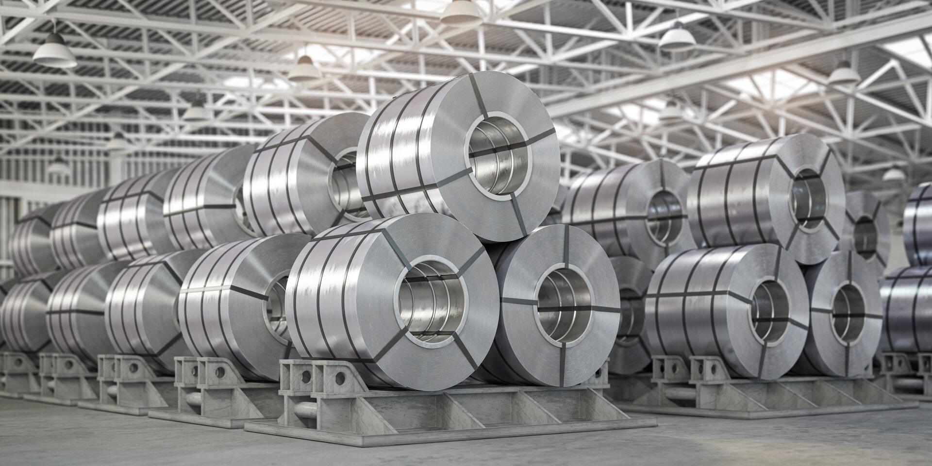
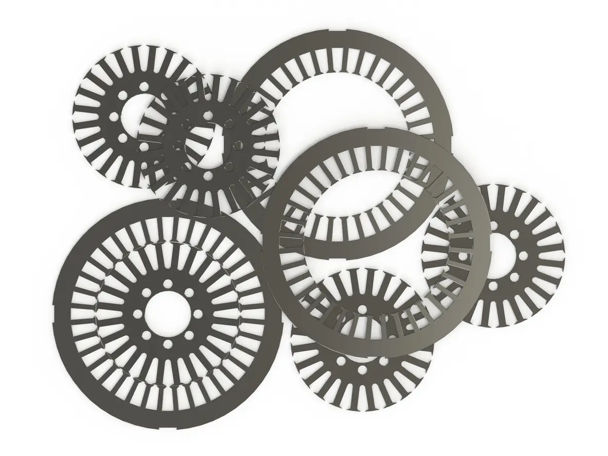
The core structure of an electric motor primarily consists of a rotor and a stator, and these components typically use silicon steel laminations of 0.5 mm thickness. These silicon steel laminations offer excellent magnetic properties, allowing the motor to effectively reduce energy losses during operation. Silicon steel is a preferred material due to its ability to minimize both hysteresis and eddy current losses, thereby enhancing the overall efficiency of the motor. The thin layer design of the laminations facilitates better heat dissipation, which helps improve the motor’s stability and extend its service life.
Silicon steel laminations are common in modern electric motors due to their lightweight, high strength, and exceptional magnetic permeability. This enables the motor to achieve higher efficiency without sacrificing mechanical strength, meeting industry demands for energy savings and emission reductions. Additionally, silicon steel laminations can effectively suppress high-frequency signals, thus reducing motor noise—another reason why they are the material of choice for high-performance motors.
1.2 Importance of Reducing Eddy Current Losses
Eddy current loss is a form of internal energy loss caused by changes in the magnetic field, mainly occurring in ferromagnetic materials like steel. When a magnetic field penetrates the steel, it induces circulating currents within the steel, generating heat. If this heat is not effectively controlled, it can lead to reduced efficiency and a shorter lifespan for the material. Using thin silicon steel laminations can significantly reduce the formation of eddy currents and keep energy losses within a reasonable range.
In motor operation, eddy currents not only increase heat generation but also cause material fatigue and insulation damage. By using insulating layers, typically varnish, between laminations, eddy currents are effectively blocked, reducing losses and maintaining stable operational efficiency. Research indicates that using silicon steel laminations of 0.5 mm thickness can reduce eddy current losses by up to 20%, enabling the motor to maintain excellent performance even under higher load conditions.
In summary, the application of silicon steel laminations in electric motors not only enhances the magnetic properties of the material but also significantly reduces eddy current formation, improving overall energy utilization. As silicon steel technology advances, motor efficiency is expected to increase further, supporting the achievement of energy-saving and emission reduction goals.
2. The Role of Silicon Steel Laminations in Reducing Eddy Current Losses
2.1 High-Precision Insulation Layers: Effectively Reducing Eddy Current Formation
In the design of motor structures, the insulation layers between steel sheets play a crucial role. Each silicon steel lamination is typically coated with a thin insulation layer to prevent current conduction between laminations. This insulation layer, usually varnish, has extremely low conductivity, effectively blocking current transmission and thus reducing the formation of eddy currents.
Eddy currents are induced by changes in the magnetic field within the laminations, forming small loops of current within the metal and causing material heating. Excessive eddy currents lead to unnecessary energy losses, which generate additional heat in the material, affecting motor efficiency and shortening its lifespan. Insulation layers reduce the probability of eddy current formation, significantly enhancing overall motor operational efficiency.
2.2 Properties of Silicon Steel in Suppressing Eddy Currents
Silicon steel is a material with high resistivity, which makes it highly effective in reducing eddy currents during motor operation. The thin layer design of silicon steel laminations is carefully calculated, focusing on how to minimize eddy currents while maintaining material strength. By using 0.5 mm silicon steel laminations, the motor’s impedance is increased, reducing eddy current pathways and achieving lower energy loss.
The high resistivity of silicon steel confines eddy currents to limited areas, reducing transverse current flow within the laminations. This means that even under high-frequency operation, silicon steel laminations can maintain low losses. Research indicates that silicon steel laminations significantly reduce eddy currents, maintaining stable operating temperatures even under high loads.
2.3 The Relationship Between Eddy Current Losses and Energy Efficiency
The reduction of eddy current losses has a direct impact on the energy efficiency of motors. In motors, each unit of consumed power affects the final energy conversion efficiency. The losses caused by eddy currents generate heat, which decreases the overall system’s efficiency. By using high-quality silicon steel laminations and precise insulation treatment, losses can be controlled under variable operating conditions, achieving better energy conversion rates.
Reducing eddy current losses enables the motor to convert input energy into mechanical energy more efficiently, providing stable output. This design not only enhances operational performance but also lowers energy consumption, reducing operational costs and maintenance needs. These advantages make silicon steel lamination technology essential for increasing energy efficiency, especially in applications requiring prolonged operation.
Conclusion The application of silicon steel laminations in electric motors effectively enhances energy efficiency by reducing eddy current losses. As technology advances, improvements in silicon steel performance and insulation techniques enable motors to maintain efficient and stable operation across broader application scenarios. These innovations strongly support future energy-efficient designs, aligning with sustainable development needs.
3. Enhancing Motor Performance with Stator Coil Insulation and Design
3.1 Copper Winding Technology for Improved Heat Dissipation
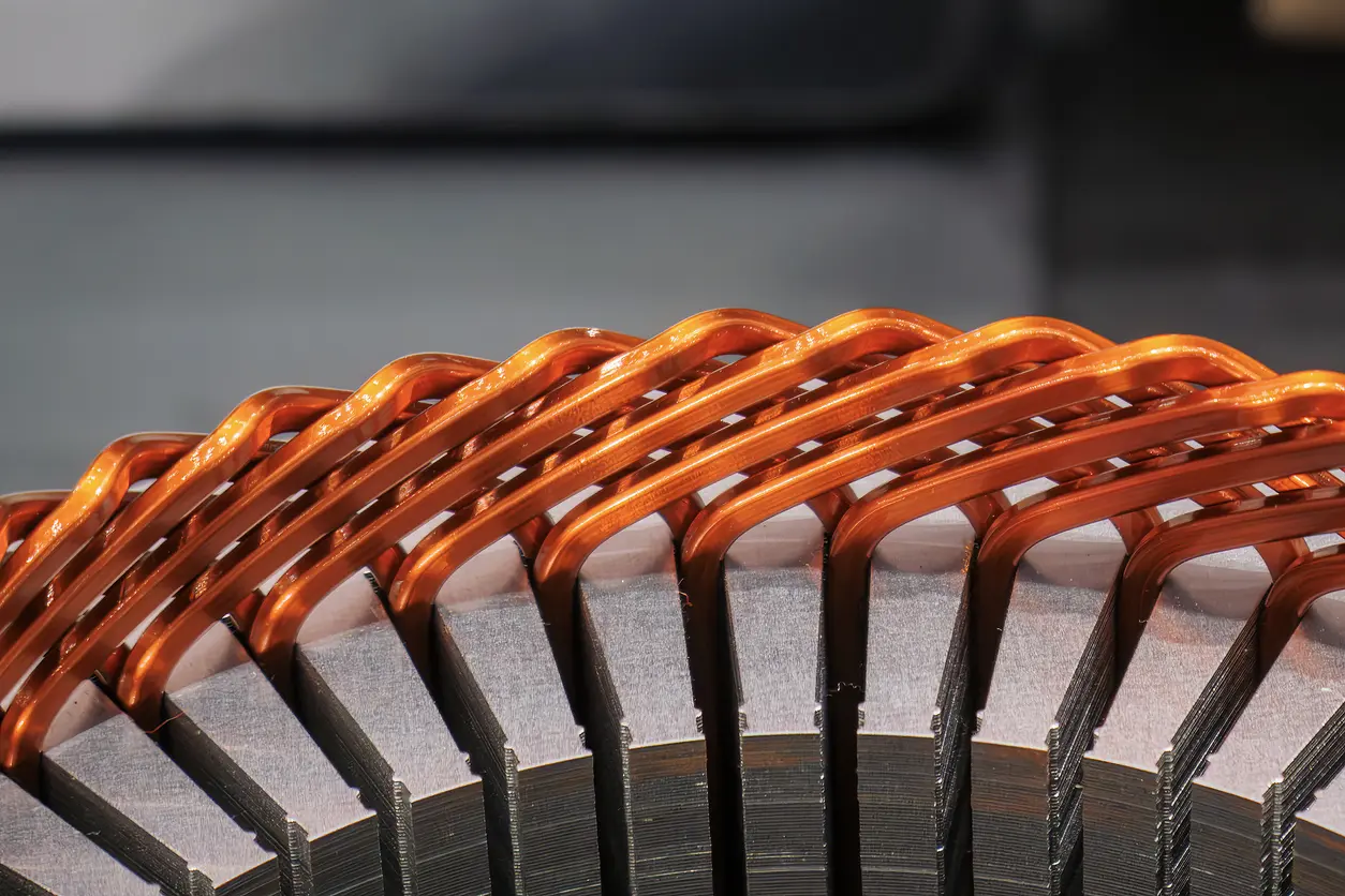
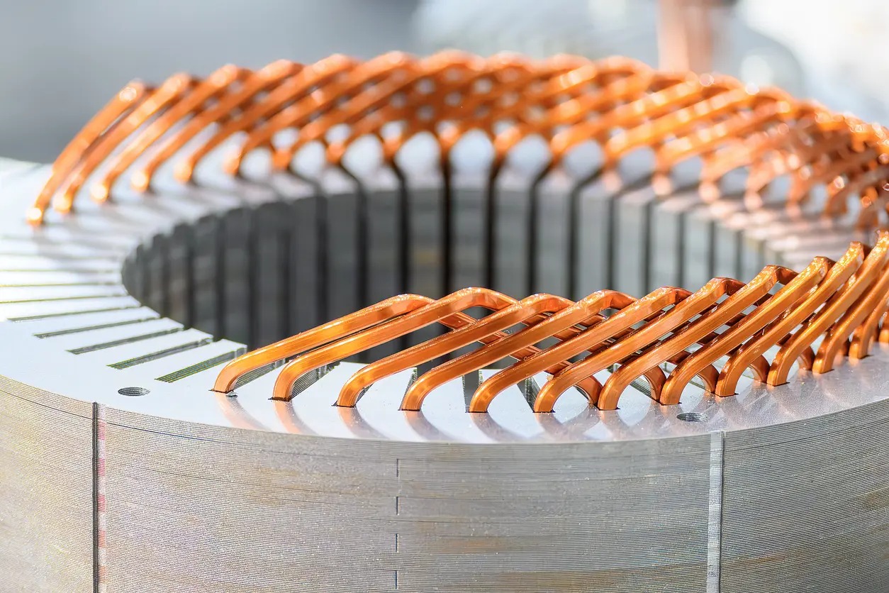
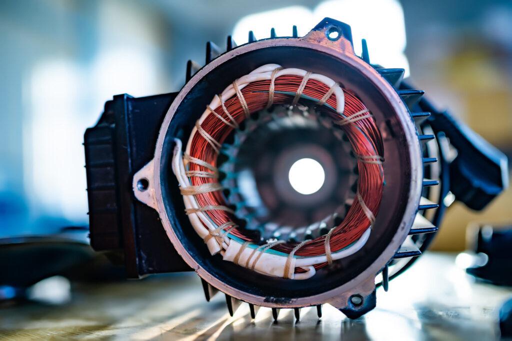
In electric motors, copper windings serve as the primary channels for current flow, directly impacting the motor’s performance and efficiency. The selection of winding materials is crucial for optimal heat dissipation. Small motors typically use round copper conductors with numerous turns per coil, suited for stable current distribution. For larger motors, thicker rectangular copper bars are preferred, allowing for higher current capacity and reduced heat generation, making them ideal for stable operation under high-power demands.
Copper’s high conductivity makes it an ideal material for windings, effectively lowering resistance and reducing energy loss while improving conduction efficiency. To prevent damage from rising temperatures, copper windings require sufficient insulation treatment to ensure long-term operational stability and reliability.
3.2 Electrical Protection Function of Coil Insulation
The winding coils of electric motors are typically covered with special insulation materials to prevent current leakage and short circuits. Most of these insulation layers are made from high-temperature polymer materials, effectively blocking current and maintaining physical stability in high-temperature environments. For more demanding applications, advanced insulation technologies, such as multi-layer insulation or varnish treatment, are used to enhance durability.
In electric motors, the choice of insulation materials affects not only operational efficiency but also equipment safety. Good insulation protects windings from external electric field interference and reduces the risk of overheating, thereby extending the motor’s lifespan.
3.3 Impact of Electrical Connection Methods
Electric motors generally use either Y (star) or Δ (delta) connections for their electrical configurations. These connections determine the current distribution between the windings and affect the motor’s starting performance and operational efficiency. Y connections are typically used during the startup phase, as they lower current requirements and reduce the load on the power grid. After reaching stable running speeds, switching to a Δ connection can increase output power, torque, and speed.
Moreover, three-phase motors usually have only three output leads, regardless of whether they use Y or Δ connections. This standardized design facilitates on-site installation and wiring, simplifying maintenance and repair. The connection type closely relates to the motor’s operational characteristics and can be adjusted flexibly based on application needs.
3.4 Integrating Insulation Protection and Heat Dissipation Technology
In motor design, heat dissipation and insulation protection are inseparable factors. Copper windings generate significant heat, requiring efficient heat dissipation techniques to maintain stable operating temperatures. Some motors enhance heat dissipation by adding cooling fans within the windings or using thermally conductive materials to improve cooling efficiency. At the same time, insulation materials must have high heat resistance to prevent failure or short circuits caused by excessive temperatures.
In modern electric motors, the precision of winding design and the application of advanced insulation technology ensure that motors maintain stable heat dissipation while operating efficiently. This integrated design approach not only improves equipment reliability but also reduces maintenance requirements, achieving lower operational costs.
4. Rotor Construction and Design: Optimizing Performance in Electric Motors
4.1 Application of Layered Steel Technology in Rotors
The core of a rotor is typically made of layered steel sheets, with this structure helping to reduce energy losses, especially eddy current losses. Insulation layers separate the steel sheets to prevent transverse current flow within the steel, reducing unnecessary heat generation. As eddy currents are a common source of energy loss in motor operation, this layered structure effectively enhances rotor efficiency and extends its service life.
The layering technique not only improves rotor efficiency but also makes the manufacturing process more flexible and economical. Each steel sheet can be precisely stamped into the required shape and size, meeting the design requirements of different types of motors. This technology reduces energy losses while optimizing the overall performance of the motor.
4.2 Characteristics of Squirrel Cage Rotor Design
The squirrel cage rotor is a common design in electric motors. This rotor features a unique slot design, typically filled with conductive materials like aluminum or copper. These conductor bars are embedded in the rotor slots and connected at both ends by ring-shaped shorting rings, forming a cage-like structure. Squirrel cage rotors do not require additional insulation layers, enabling them to operate stably under high loads with durability.
In low-power motors, the squirrel cage is often made from aluminum to reduce manufacturing costs and provide effective cooling. For high-power motors, more durable copper or brass bars are welded for increased strength. Regardless of the material used, this structure has high mechanical stress resistance, making it suitable for demanding operating environments.
4.3 Relationship Between Slot Design and Torque-Speed Characteristics
The shape of the rotor slots significantly impacts the operational characteristics of an electric motor. Different slot shapes can alter the torque-speed curve of the rotor, allowing the motor to operate stably under various load conditions. For example, sawtooth-shaped slots are typically used in motors with high starting torque, ideal for applications requiring rapid acceleration.
Additionally, rotor slot shapes can affect torque ripple and operational noise. Optimizing slot design can ensure smooth motor operation at different speeds, reducing vibrations and noise, thereby enhancing overall user experience and extending service life.
4.4 Cooling Efficiency of Aluminum Squirrel Cage Rotors
In squirrel cage rotors, aluminum is used not only for the conductor bars and shorting rings but also to integrate fan blades for enhanced cooling. These fan blades are usually cast directly onto the aluminum cage, and as the rotor rotates, the blades provide airflow within the motor, effectively dissipating heat and reducing internal temperatures. This design is particularly beneficial for high-power applications.
5. Starting Characteristics and Control Methods in Electric Motors
5.1 Starting Current and Torque Characteristics
Electric motors experience an initial surge in current and torque during startup. Since the rotor lacks any kinetic energy while at rest, when power is applied, the stator coils immediately generate a rotating magnetic field that induces current in the rotor. This current causes the rotor to spin and produce torque. However, the starting current can be four to seven times higher than the normal operating current, and the starting torque is typically between 1.75 and 2.5 times the rated torque. Such high starting current can lead to overheating or damage to the system, so appropriate control measures are necessary to limit the starting current.
5.2 Reduced-Voltage Starting Methods
In some cases, directly starting the motor can cause excessive voltage fluctuations on the grid, which may affect other equipment. Reduced-voltage starting becomes one solution. With this method, the starting voltage is usually reduced to 70% to 80% of the rated voltage, which can be achieved using a step-down transformer or an autotransformer. The reduced voltage cuts the starting current to around 56% of the full-voltage starting current, and although the starting torque also decreases, this method is suitable for starting motors with smaller loads.
Another common reduced-voltage starting method is the “star-delta” start. Here, the motor’s stator windings are first connected in a star configuration, and then switched to a delta configuration after startup. This further reduces the starting current and impact on the grid, helping to extend motor life and reduce the load on the electrical system.
5.3 Series Resistance or Inductance Starting
For large motors that require starting current control, series resistance or inductance is a common starting method. During startup, series resistors or inductors are added to the stator circuit to limit the current flowing through it. As the motor gradually accelerates, these resistors or inductors can be gradually removed, allowing it to reach normal operation. This method is suitable for high-inertia load startups and helps reduce the risk of rotor overheating.
5.4 Variable Frequency Starting
Using variable frequency drives (VFDs) allows for more flexible control over motor startup. By adjusting the frequency and voltage supplied to the stator, a VFD can smoothly increase the motor’s speed without producing excessive starting current. This startup method is particularly suited for large equipment requiring gradual acceleration, as it effectively reduces the current demand during startup and prevents rotor overheating. VFDs also provide speed control during operation, making them ideal for applications requiring precise control of speed and torque.
5.5 Impact of Starting Control on Motor Life
The choice of startup method has a direct impact on motor lifespan. High starting current can lead to overheating of the stator windings and rotor, damaging insulation materials and shortening the motor’s life. Therefore, selecting an appropriate starting method based on load requirements is essential. For high-inertia loads, using reduced-voltage or variable frequency starting can minimize the sudden impact on the motor, extending its operational lifespan. Additionally, temperature monitoring during motor operation is crucial. Timely monitoring and protective measures can effectively prevent failures due to overheating.
A suitable starting method not only helps protect the motor’s internal components but also has long-term implications for system stability and overall operational costs.
6. Role of Bearings and Cooling Systems in Electric Motors
6.1 Bearing Design and Function
The bearing system in an electric motor primarily supports the rotor, ensuring stable operation with high performance. Bearings must withstand the dynamic loads from the rotor and maintain minimal friction during the motor’s operation. This reduces energy loss and extends the motor’s service life. Depending on operational conditions and design requirements, bearings are typically either ball bearings or plain bearings. Ball bearings are suitable for high-speed operation with minimal maintenance, while plain bearings excel in low-speed applications that need to support heavy loads.
6.2 Lubrication and Maintenance of Bearings
Bearing lubrication is key to ensuring the long-term stability of electric motors. Lubricants reduce internal friction and wear, as well as heat generation. Common lubrication methods include grease and oil bath lubrication, depending on the bearing type. Grease lubrication suits well-sealed bearings with longer maintenance intervals, whereas oil bath lubrication is suited for heavy-duty bearings that need frequent maintenance. Regular lubrication and inspection can extend bearing life and prevent failures due to wear or overheating.
6.3 Types of Cooling Systems
Electric motors generate considerable heat during operation, and the cooling system’s role is to dissipate this heat promptly to keep the motor within a safe temperature range. The type of cooling system varies based on the motor’s size and operating environment. Common cooling methods include air cooling and water cooling. Air-cooled systems use fans to draw external air into the motor, suitable for small to medium-sized equipment, while water-cooled systems use water circulation, ideal for large equipment requiring efficient heat dissipation.
6.4 Maintenance and Monitoring of Cooling Systems
Regular maintenance and monitoring are essential for long-term efficiency of cooling systems. Fans and heat sinks in air-cooled systems should be cleaned regularly to prevent blockage from dust and debris, which can impair cooling. In water-cooled systems, the water pathways need to be checked for blockages, and coolant should be replaced periodically to prevent scaling or corrosion. Advanced electric motors may also have temperature sensors and monitoring devices that can automatically adjust the cooling system or trigger alarms if temperatures exceed the set range.
6.5 Impact of Bearings and Cooling Systems on Motor Performance
Bearings and cooling systems are vital not only for the reliability of electric motors but also directly impact overall performance. Well-designed bearings and lubrication significantly reduce friction, enhancing operational efficiency, while an efficient cooling system prevents downtime or damage due to overheating. Choosing suitable cooling methods and implementing regular maintenance can extend motor lifespan and lower maintenance costs, achieving optimal economic benefits. With the right bearing and cooling configuration, electric motors can operate stably across various loads and environmental conditions, ensuring long-term, efficient operation.
7. Applications and Future Developments of Drive Technologies in Electric Motors
7.1 Frequency Adjustment and Drive Control Technology
Drive control technology plays an important role in electric motor applications, particularly in frequency adjustment and speed control. Variable Frequency Drives (VFD) are common control tools that adjust motor input frequency to control speed. As frequency increases or decreases, motor speed changes accordingly, improving operational efficiency and helping to reduce energy consumption. VFDs have wide applications, especially in industrial production, where they control the start-up and shutdown of high-power equipment.
7.2 Applications of Direct Current Drive Technology
In specific applications, direct current (DC) drive systems are still popular due to their high precision and responsiveness. DC drive systems offer simple yet precise speed control, suitable for scenarios requiring frequent start-stop operations and precise speed adjustments, such as production lines and conveyors. With advancements in power electronics, DC drive systems continue to improve in performance and efficiency, making them very economical and efficient for small- to medium-sized equipment.
7.3 Energy-Saving Technologies in Drive Systems
As environmental awareness and energy costs rise, energy-saving technologies in drive systems are increasingly important. Adaptive control systems can optimize motor operating parameters in real-time according to load conditions, achieving the best energy-saving effect. Additionally, power factor correction technology is often used to improve system efficiency and reduce inactive power consumption. Installing power factor correction devices allows businesses to lower electricity costs while reducing the load on the power system.
7.4 Integration of Intelligent Drives and the Internet of Things
Future drive technology trends include the integration of intelligence and the Internet of Things (IoT). Intelligent drive systems utilize sensors and data analytics to monitor motor status in real-time, optimizing control strategies based on live data. Through IoT platforms, drive systems can interconnect with other equipment for remote monitoring and maintenance, improving management efficiency and reducing downtime. These technologies play a key role in enhancing production automation and intelligence levels.
7.5 Challenges and Opportunities in Future Drive Technology
Despite rapid development in drive technology, future challenges remain, including increasing demand for high-efficiency energy-saving solutions and reliance on new materials and technologies. To meet higher environmental and efficiency standards, drive technology needs continuous breakthroughs in energy-saving materials and design innovations. On the other hand, advances in artificial intelligence and big data analytics present new opportunities for drive systems. By analyzing operational data in-depth, systems can predict potential issues and carry out preventive maintenance, extending motor life and reducing operational costs. With technological progress, drive systems will continue to evolve towards greater intelligence and environmental sustainability.

8. Environmental Benefits and Future Prospects of Lamination Technology
8.1 Environmental Benefits of Lamination Technology
As the concept of sustainable development becomes more widespread, lamination technology in electric motors makes significant contributions to environmental protection. Materials used in this technology are typically low-loss and high-efficiency steels, reducing energy consumption during motor operation. Compared to solid materials, laminated structures effectively reduce eddy current losses, allowing motors to operate with higher efficiency, thereby reducing overall carbon emissions. This not only conserves energy but also aligns with global carbon neutrality goals.
8.2 Potential of Using Recycled Materials
Another major environmental advantage of lamination technology is its potential for using recycled materials. With advances in recycled steel technology, more and more motor manufacturers are considering the use of recycled steel instead of traditional steel sheets, which reduces dependence on natural resources and lowers the carbon footprint. The strength and performance of recycled steel are sufficient to support laminated structures, enabling motors to maintain high efficiency while being more sustainable.
8.3 Integration with Future Energy-Saving Technologies
With technological progress, laminated structures are expected to integrate with more energy-saving technologies. In the future, lamination technology in electric motors may incorporate intelligent control systems that adjust operating parameters based on real-time conditions to achieve optimal energy-saving results. Moreover, the development of adaptive control systems will further promote the application of lamination technology, precisely controlling flux distribution to reduce losses and further enhance energy efficiency.
8.4 Manufacturing Technologies to Reduce Waste
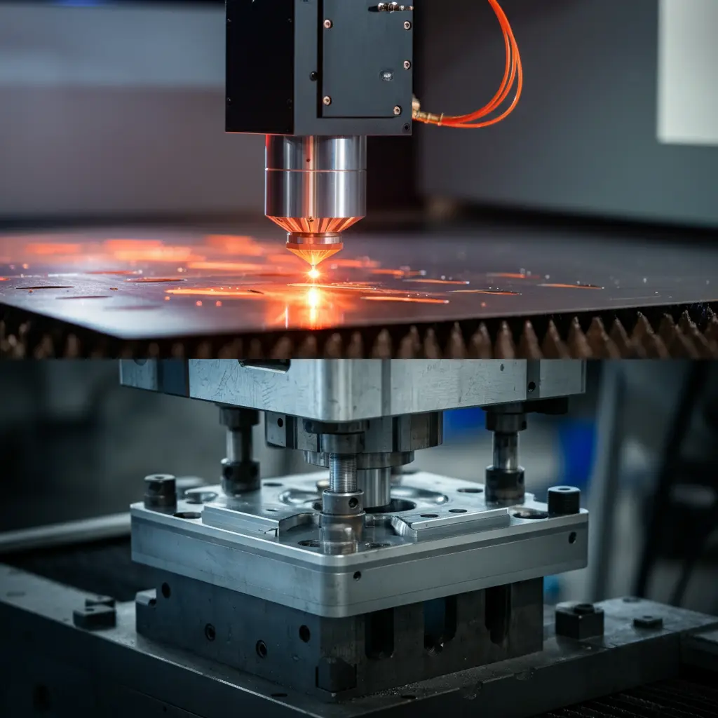
The electric motor manufacturing industry can also effectively reduce waste generation during the application of lamination technology. Through precision stamping and laser cutting, manufacturers can control the cutting and stacking of materials precisely, reducing material waste and environmental impact. Additionally, modern manufacturing processes can facilitate waste recovery and reuse, making the entire production process more eco-friendly.
8.5 Future Environmental Prospects
Looking ahead, lamination technology in electric motors will have even broader applications. With the introduction of artificial intelligence and IoT technology, the environmental performance of electric motors will improve further. Future motors may feature self-diagnosis and preventative maintenance functions to reduce energy consumption and extend service life. These technological advancements not only bring new opportunities to the electric motor industry but also contribute to achieving sustainable development goals. Through continuous innovation and optimization, lamination structures will become crucial pillars for the green development of the electric motor industry.
※Further Reading: What is motor lamination ?
Source reference from: https://www.researchgate.net/

