Range anxiety sits at the heart of every EV engineering decision. Designers can install the largest battery pack on the market, but if the traction motor bleeds energy as waste heat, the driver still pulls over short of the destination. One of the most consequential — and least visible — answers to that problem is laminated stator core design: a technique that turns what looks like a solid block of steel into thousands of electrically isolated micro-thin sheets, each one quietly winning a small battle against wasted energy.
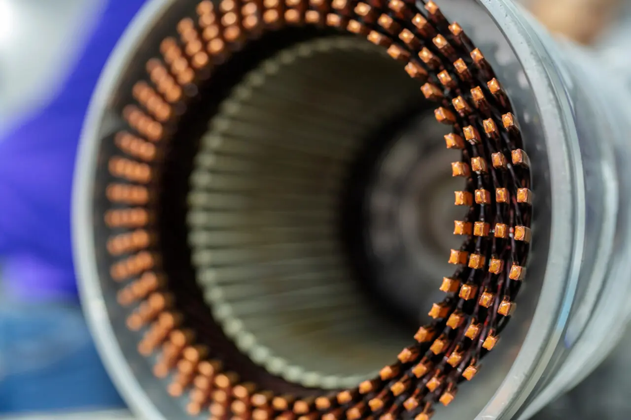
Whenever I look at a teardown of a modern EV traction motor, I’m always struck by the stator. To the naked eye it looks like a solid block of steel. Run a fingernail across it, though, and you realize it is actually hundreds of thin-gauge sheets stacked together. For a deeper look at how the stator itself is constructed and why it sits at the center of motor performance, this guide to electric motor stator fundamentals is an excellent starting point. It is a brilliant reminder that in EV engineering the biggest efficiency gains often hide in the microscopic details — and laminated stator core design is the best example of that principle in the entire powertrain.
The Physics of the Problem: What Are Eddy Currents?
To understand why laminated stator core design matters, you first need to understand what it is fighting. By Faraday’s Law of Induction, any conductor inside a changing magnetic field will have a voltage induced across it. In an AC traction motor, the stator’s magnetic field reverses direction hundreds of times per second. The steel core — a perfectly good electrical conductor — responds exactly as Faraday predicted: localized, swirling currents form inside it. These are eddy currents.
Eddy currents do no useful work. They obey Joule’s Law (P = I²R) and convert electrical energy directly into heat. At the switching frequencies demanded by a modern EV inverter — often 400 Hz and above at highway speeds — this waste can be enormous, draining the battery pack while simultaneously pushing stator temperatures toward the point where permanent magnets begin to demagnetize. The entire purpose of laminated stator core design is to interrupt these currents before they can form. The U.S. Department of Energy’s Electric Drive Technical Team Roadmap identifies low-loss electrical steel and advanced lamination techniques as key materials priorities for meeting next-generation EV traction motor targets.
The governing empirical formula for eddy current loss is:
Pe = ke × f² × B²max × d²
Where ke is a material-dependent constant, f is frequency, Bmax is peak magnetic flux density, and d is lamination thickness. The critical insight is that d is squared. Cut the sheet thickness in half and eddy current losses fall by a factor of four. That single mathematical relationship is the entire engineering rationale behind every laminated stator core design decision made in a modern motor plant.
Solid vs. Laminated Core: Why One Works and the Other Doesn’t
Early or low-cost motor designs use a solid steel stator. At low frequencies — a workshop drill, a washing machine — the losses are tolerable. Scale that design up to an EV traction motor spinning at 15,000 RPM and the consequences are catastrophic. The table below shows exactly what laminated stator core design changes:
| Feature / Metric | Solid Steel Stator Core | Laminated Stator Core Design | Impact on EV Performance |
|---|---|---|---|
| Current Path | Unrestricted; large circular paths through bulk steel | Restricted by insulating coatings between each sheet | Less wasted energy in the stator |
| Heat Generation | Extremely high — risks permanent magnet demagnetization | Low to moderate; manageable via active cooling | Higher continuous power output without thermal shutdown |
| Eddy Current Loss (Pe) | Grows exponentially with RPM | Drastically reduced (Pe ∝ d²) | Direct increase in battery range and system efficiency |
| Best Use Case | DC electromagnets, low-frequency industrial tools | High-frequency AC traction motors in EVs | Essential for modern high-speed electric powertrains |
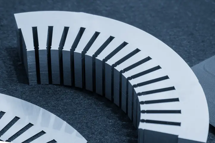
How Laminated Stator Core Design Actually Works
The mechanism behind laminated stator core design is elegantly simple. Eddy currents need a continuous conductive loop to flow. By slicing the core perpendicularly to the magnetic flux path, each thin sheet becomes its own isolated island. The induced voltage is still there — Faraday’s Law cannot be repealed — but the current has nowhere to go. The circuit is broken.
The slice alone is not sufficient. Each lamination in a proper laminated stator core design is coated with a thin insulating layer — typically a C4 or C5 inorganic oxide or varnish coating just a few micrometres thick. Without it, even microscopic surface contact between sheets would re-establish the conductive path and partially restore the very losses the laminated stator core design is trying to eliminate.
High-RPM motors make this non-negotiable. The carbon-sleeved rotors and high-frequency stators in machines like the Tesla Model S Plaid or the Lucid Air push electrical frequencies so high that the thermal consequences of an inadequate laminated stator core design would be immediate and irreversible.
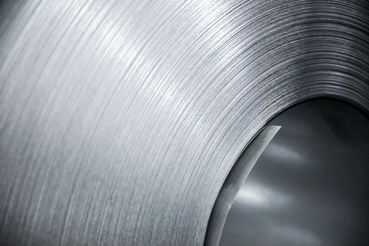
Material Selection: The Role of Electrical Steel
A well-executed laminated stator core design is only half the answer. The other half is material chemistry. Standard structural steel has an electrical resistivity of roughly 10 µΩ·cm. Add approximately 3–3.5% silicon to the alloy and resistivity climbs to around 50 µΩ·cm. Higher resistivity means a weaker induced current for the same induced voltage — a direct reduction in I²R loss that works alongside, not instead of, the laminated stator core design.
As Charged EVs notes in its deep-dive on traction motor efficiency, the vast majority of motors today use silicon-alloyed steel for the magnetic circuit precisely because it combines high saturation flux density, good formability, and high electrical resistance at a commercially viable cost. Non-oriented silicon steel (NO-SiFe) is the industry standard for EV traction motors because the magnetic flux rotates in all directions within the stator plane as the motor turns. The “non-oriented” designation means the material’s magnetic properties are isotropic — equally favourable in every in-plane direction — which is exactly what a rotating machine requires from its laminated stator core design.
| Steel Grade / Thickness | Relative Eddy Current Loss | Manufacturing Complexity | Typical EV Application |
|---|---|---|---|
| Standard (0.50 mm) | 100% (Baseline) | Low — easy to stamp and stack | Older EVs; low-speed hybrid traction motors |
| Thin (0.35 mm) | ~49% of baseline | Medium — standard production tooling | Most modern mass-market EVs (e.g. Chevy Bolt, Nissan Leaf) |
| Ultra-Thin (0.20–0.25 mm) | ~16–25% of baseline | High — requires laser cutting or advanced stamping | High-performance sports EVs, Formula E, hypercars |
The data above illustrates the law of diminishing returns in laminated stator core design. Moving from 0.50 mm to 0.35 mm is largely a stamping-die upgrade — accessible for any volume manufacturer. Moving further to 0.20 mm slashes losses by an additional 30+ percentage points, but tooling investment and sheet-handling complexity grow sharply. The current automotive sweet spot for laminated stator core design sits between 0.25 mm and 0.35 mm, with premium powertrain programmes pushing toward the thinner end.
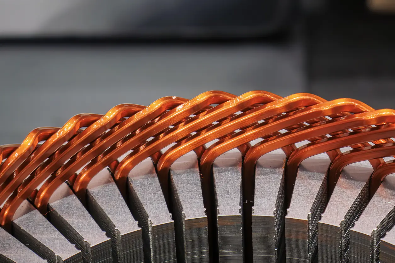
Manufacturing the Core: Stacking Without Short-Circuiting
Every laminated stator core design creates an immediate production paradox: thousands of insulated sheets must hold together as a rigid structural component without their insulating coatings being bridged or destroyed in the process. How the sheets are bonded turns out to matter almost as much as how thin they are — a poorly assembled laminated stator core design can surrender a significant fraction of its theoretical efficiency advantage at the bonding stage.
| Assembly Method | How It Works | Impact on Insulation / Eddy Currents | EV Industry Adoption |
|---|---|---|---|
| TIG / Laser Welding | A weld bead runs down the outside of the stacked pack | High disruption — melts insulation at the weld, creating localised short-circuit paths | Decreasing; limited to low-cost or low-frequency applications |
| Mechanical Interlocking | Tabs punched into each sheet press-fit into the sheet below | Moderate — slightly disrupts flux path but far better than welding | Very common; strong balance of production speed and efficiency |
| Adhesive Bonding (Backlack) | Heat-curing resin coats each sheet; oven-baked to form a monolithic block | Zero physical disruption to sheets or insulation coatings | Rapidly growing; preferred for premium, high-efficiency powertrains |
Backlack bonding deserves particular attention. The thermosetting resin pre-applied to each sheet cures when the full stack is oven-baked, locking every lamination in place without a single weld or punch. A peer-reviewed review of laminated electrical steel joining methods published in Materials (MDPI) confirms that both mechanical interlocking and fusion welding increase eddy current losses by creating conductive bridges between sheets — reinforcing why adhesive bonding has become the assembly method of choice for any laminated stator core design programme where efficiency targets are ambitious.
The Future of Laminated Stator Core Design in Electric Vehicles
Silicon steel laminations have dominated for decades, but two emerging technologies are beginning to challenge the conventional laminated stator core design at the performance frontier.
Amorphous metal cores — produced by rapid-quenching molten alloy onto a spinning drum — have no crystalline grain structure at all. The result is hyper-low coercivity and resistivity far beyond any conventional silicon steel, with eddy current losses reduced by up to 80% compared to today’s best-grade laminated stator core design materials. The trade-off is brittleness and a manufacturing process not yet cost-competitive at automotive scale.
Separately, axial flux motor architectures — where the rotor and stator face each other across an air gap rather than sitting concentrically — require laminations wound in a spiral rather than stamped and stacked. This rolling lamination approach is technically demanding but enables extremely compact, high-torque-density machines that several EV and aerospace programmes are actively productionising, creating an entirely new vocabulary of laminated stator core design challenges.
Frequently Asked Questions
Why can’t EV motors use a solid steel core?
Solid steel allows eddy currents to flow freely through a large conductive volume when exposed to high-frequency magnetic fields. A solid core has no equivalent of the circuit-breaking effect that laminated stator core design provides, so it generates immense I²R heat, destroys efficiency, and at EV operating frequencies can physically damage the motor through thermal runaway or magnet demagnetisation.
What is the ideal thickness for EV stator laminations?
There is no single universal answer, but the current automotive sweet spot for laminated stator core design is 0.25 mm to 0.35 mm. Thinner sheets reduce losses further — validated by the d² relationship in the eddy current formula — but require substantially higher tooling investment and more careful handling during assembly.
Does laminated stator core design reduce hysteresis loss as well?
No. Laminated stator core design exclusively targets eddy current losses by breaking the conductive circuit. Hysteresis loss is reduced through material chemistry — primarily by increasing the silicon content of the steel, which lowers magnetic coercivity and makes domain-wall reversal energetically cheaper.
Conclusion
Laminated stator core design is one of the unsung heroes of EV range. It does not appear on a spec sheet, it adds no visible feature to a vehicle, and yet it is the reason a modern traction motor can sustain 400+ Hz operation without melting. The relationship is unambiguous: thinner laminations, better insulation, and smarter bonding translate directly into fewer watts lost as heat and more kilowatt-hours delivered to the wheels.
From the silicon steel grade chosen to the curing temperature of the backlack adhesive, every detail of a laminated stator core design is an engineering argument against waste. In an industry where competitive advantage is measured in single-digit percentage points of efficiency, those arguments add up fast. Understanding laminated stator core design is, ultimately, understanding why modern EVs go as far as they do on a single charge.ign is, ultimately, understanding why modern EVs go as far as they do on a single charge.