Table of Contents
Introduction
Electric motor stators represent the fundamental stationary component that transforms electrical energy into controlled magnetic fields, enabling the precise operation of motors across countless industrial and consumer applications. Learn more about the fundamentals of electric motors.
Understanding stator design, construction, and failure modes is essential for engineers, technicians, and maintenance professionals seeking to optimize motor performance and reliability.
This comprehensive guide examines the critical role of stators in electric motor operation, their construction principles, material selection criteria, and practical troubleshooting methodologies. From basic component identification to advanced failure analysis, readers will gain the basic technical knowledge necessary to evaluate, specify, and maintain electric motor stators effectively.
The following sections provide detailed analysis of stator anatomy, performance characteristics, and quality considerations that directly impact motor efficiency, longevity, and operational costs in industrial environments.
What is an Electric Motor Stator? The Heartbeat of Motion
The electric motor stator functions as the stationary electromagnetic component that generates the rotating magnetic field necessary for motor operation. Without a properly functioning stator, electric motors cannot produce the controlled magnetic environment required to induce rotor motion and generate mechanical torque.
Core Definition: The Stator’s Primary Role
The stator serves as the stationary component of rotary electric machines, housing field windings that carry alternating or direct current to create precisely controlled magnetic fields. When energized, these windings generate a rotating magnetic field pattern that interacts with rotor conductors or permanent magnets to produce rotational force.
The stator’s electromagnetic design determines fundamental motor characteristics including torque output, speed range, efficiency, and power factor. Proper stator construction ensures optimal flux distribution, minimizes energy losses, and provides the structural foundation for reliable long-term operation.
Stator vs. Rotor: A Tale of Two Components
The fundamental distinction between stator and rotor components lies in their physical state during motor operation and their specific electromagnetic functions within the machine assembly.
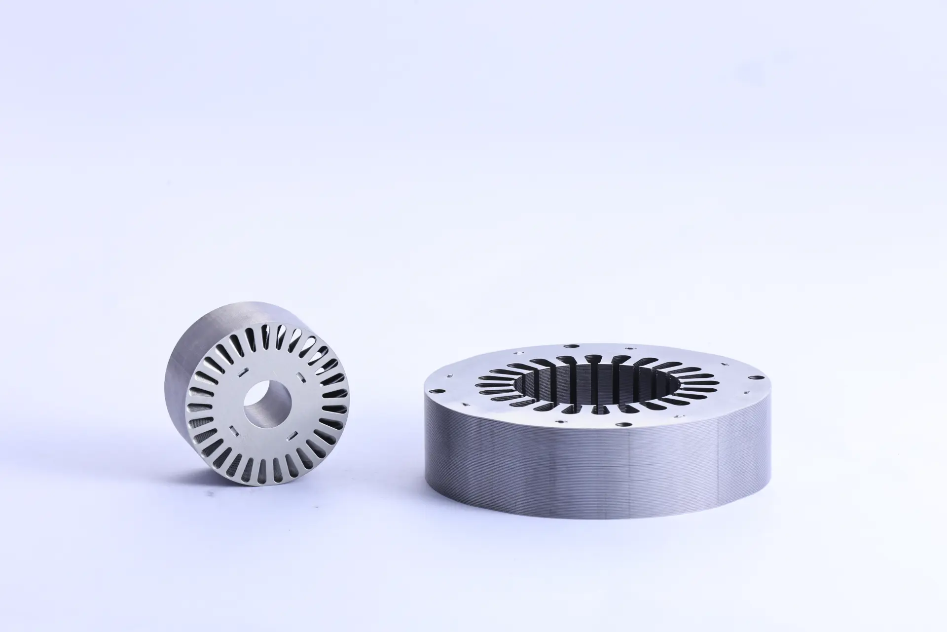
Table 1: Stator vs. Rotor at a Glance
| Feature | Stator | Rotor |
|---|---|---|
| State | Stationary | Rotating |
| Primary Role | Creates a rotating magnetic field | Interacts with the magnetic field to create torque |
| Core Component | Field Windings (Coils) | Conductor Bars or Permanent Magnets |
| Location | Outer part, fixed to the frame | Inner part, attached to the motor shaft |
The stator creates the electromagnetic environment that drives rotor rotation, while the rotor responds to this field through electromagnetic induction or magnetic attraction forces. This fundamental interaction principle governs all electric motor operation, from small servo motors to large industrial drives.
The Anatomy of a Stator: Breaking Down the Core Components
Electric motor stators comprise multiple integrated components that work together to generate controlled magnetic fields with minimal energy loss. Each component serves specific electromagnetic and structural functions critical to overall motor performance.
Table 2: Stator Component Breakdown
| Component | Material Example | Primary Function |
|---|---|---|
| Stator Core | Laminated Silicon Steel | Channels the magnetic field and reduces energy loss |
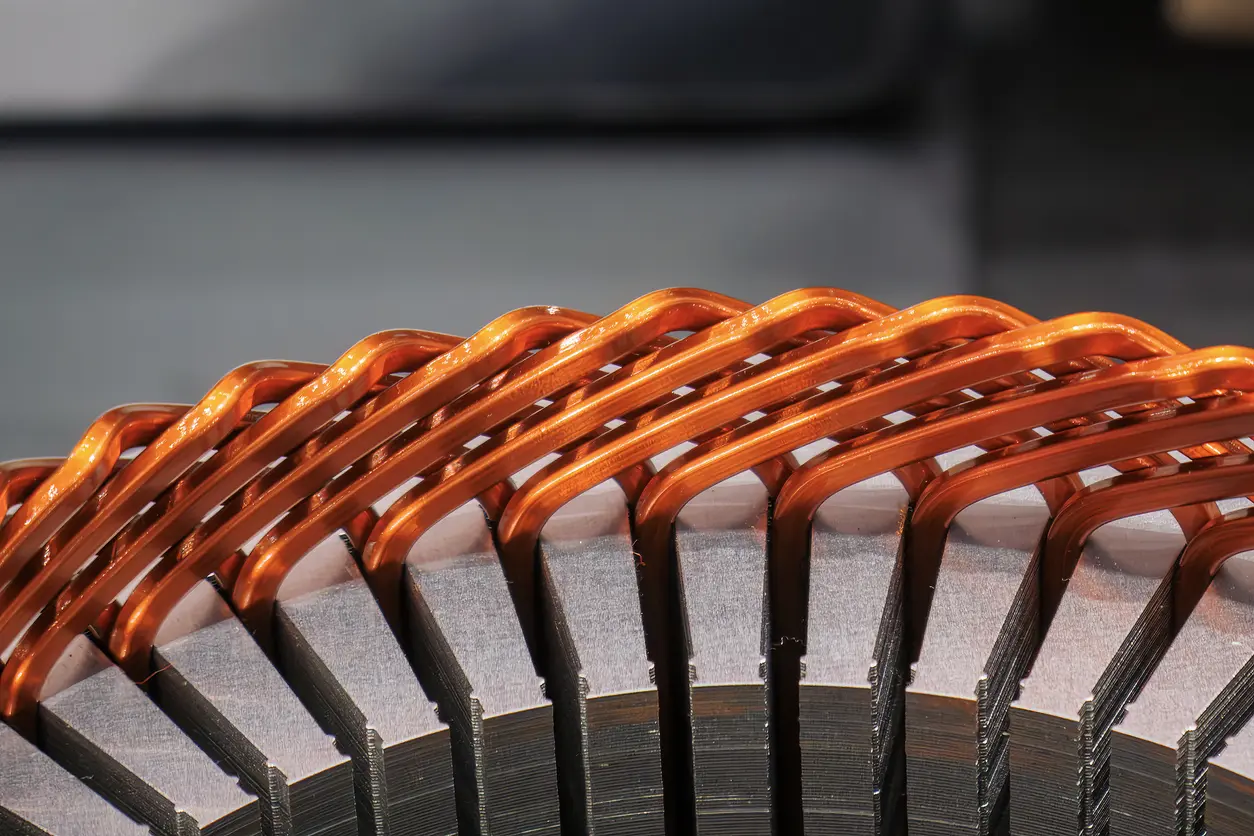
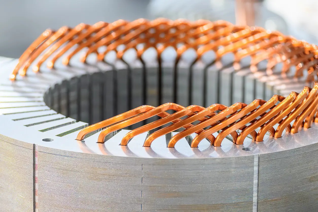
| Stator Windings | Insulated Copper Wire | Carries electric current to generate the magnetic field |
| Insulation | Varnish, Slot Liners | Prevents short circuits between windings and the core |
| Stator Frame | Cast Iron or Aluminum | Provides structural support and heat dissipation |
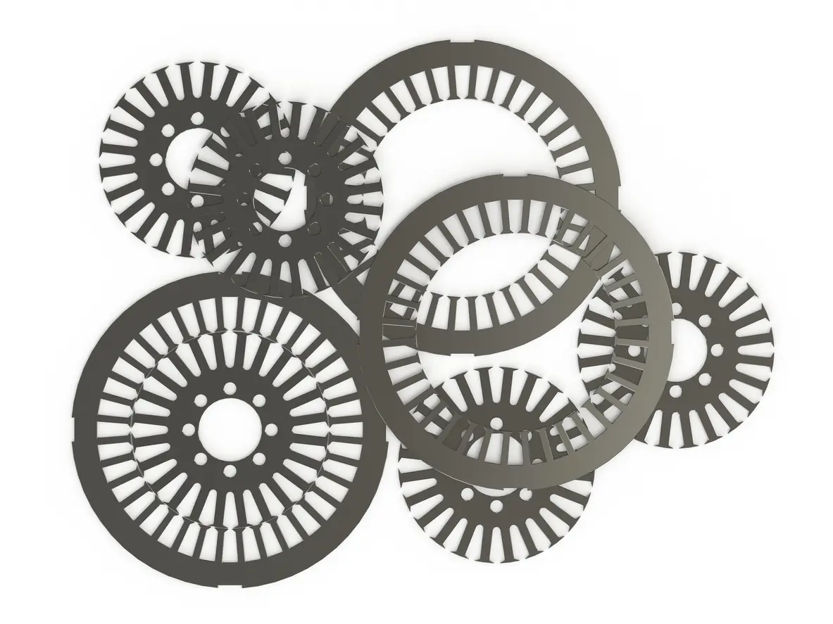
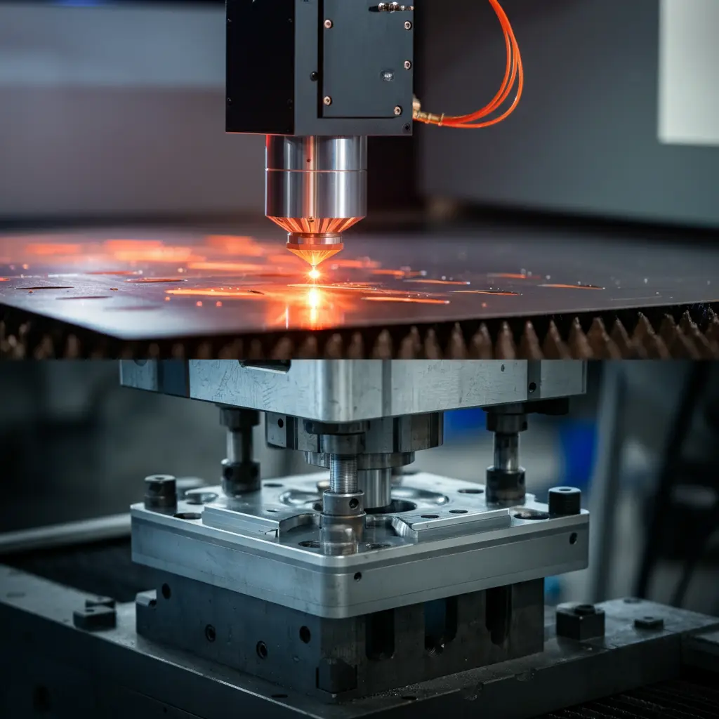
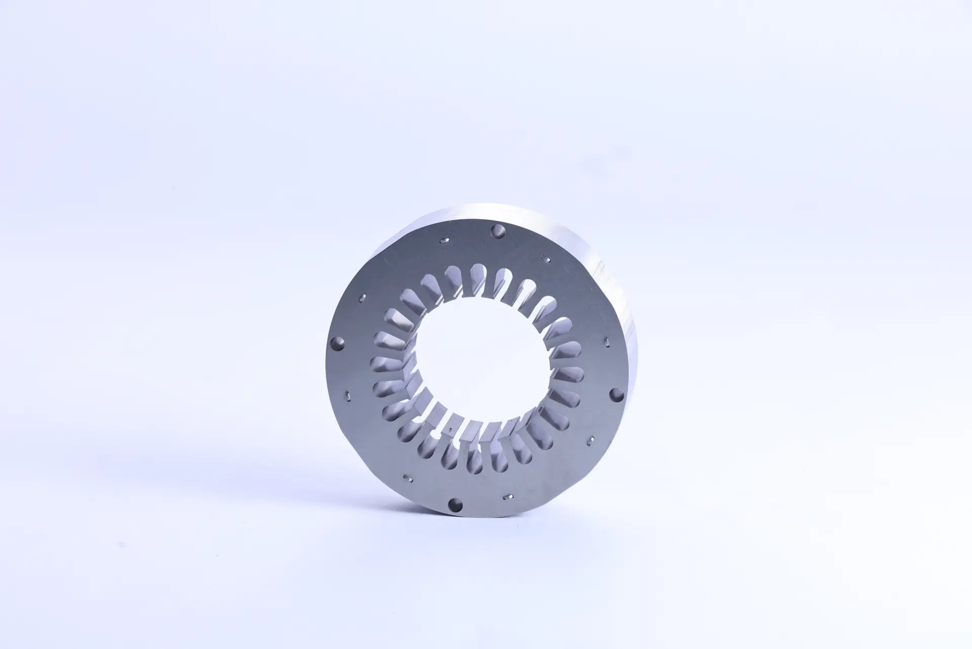
The stator core consists of stacked electrical steel laminations that provide a low-reluctance path for magnetic flux while minimizing eddy current losses through lamination isolation. These laminations are precision-stamped to create slots for winding placement and maintain consistent air gap geometry.
Stator windings are constructed from insulated copper conductors wound in specific patterns to generate the desired magnetic field distribution. Winding configuration determines motor characteristics such as pole count, voltage rating, and torque-speed characteristics.
Insulation systems protect windings from electrical breakdown and mechanical damage. High-quality insulation materials maintain dielectric strength under thermal stress, humidity, and voltage transients throughout the motor’s operational life.
From extensive field experience, insulation failures represent the most common cause of stator-related motor breakdowns. Microscopic degradation in insulation integrity—often invisible during routine inspection—frequently precipitates catastrophic winding failures. This emphasizes the critical importance of specifying appropriate insulation materials and maintaining proper operating conditions.
Stator Core Designs and Materials: The Foundation of Performance
Stator core design and material selection directly influence motor efficiency, power density, manufacturing cost, and electromagnetic performance characteristics. For access to advanced materials, innovative stator core designs, and expert support, visit Yucca Manufacturing—a trusted resource for high-performance electric motor stator solutions. Different applications require specific core configurations optimized for their operational requirements.
Common Stator Core Designs
Modern stator cores employ three primary construction methodologies, each offering distinct advantages for specific motor applications and performance requirements.
Laminated cores utilize thin electrical steel sheets stacked and bonded together, providing cost-effective construction with excellent magnetic properties for most motor applications. The lamination thickness typically ranges from 0.15 to 0.65 mm, with thinner laminations reducing eddy current losses at higher frequencies.
Segmented cores feature individual tooth sections that allow higher slot fill factors and simplified winding processes. This construction method enables greater copper utilization and improved thermal management in high-performance applications.
Sintered cores employ soft magnetic composite (SMC) materials that enable complex three-dimensional flux paths but sacrificing the maximum magnetic flux density (Bmax) due to SMC magnetic density saturation limit.
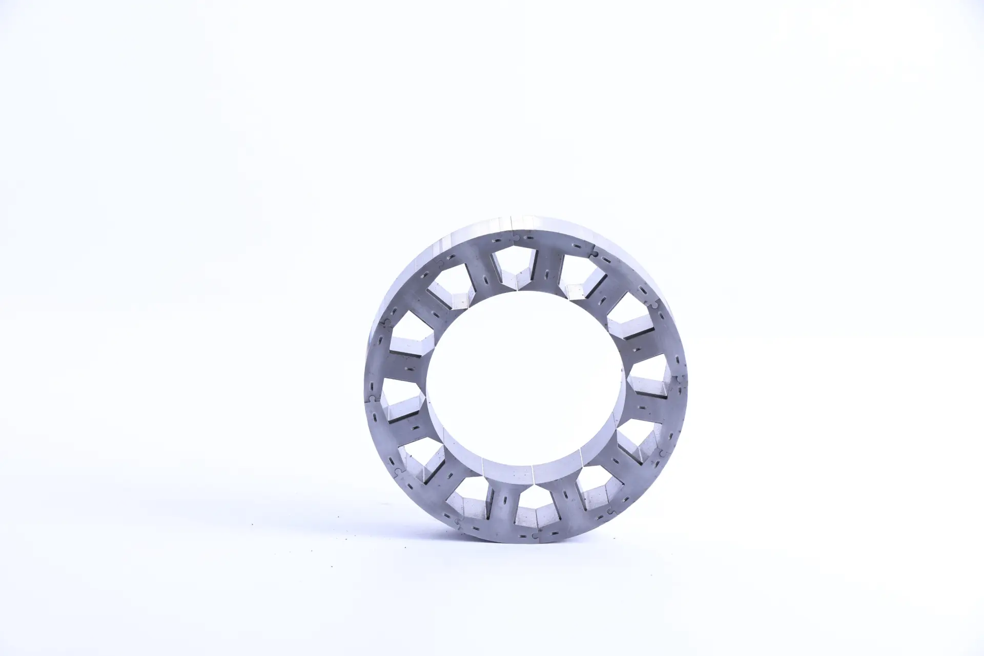
Table 3: Comparison of Stator Core Designs
| Core Design | Key Advantage | Best Application Example |
|---|---|---|
| Laminated | Widely available, reduces eddy currents | High-performance motos of various kinds |
| Segmented | High copper slot fill density, efficient | High-performance servo motors |
| Sintered (SMC) | Enabled complex 3D magnetic flux paths | Axial-flux stator, complex stator geometry |
Stator Core Materials
Electrical steel grades with high magnetic permeability and low core loss characteristics form the foundation of efficient stator construction. Silicon content typically ranges from 1.5% to 6.5%, with higher silicon content reducing core losses while increasing material cost and brittleness.
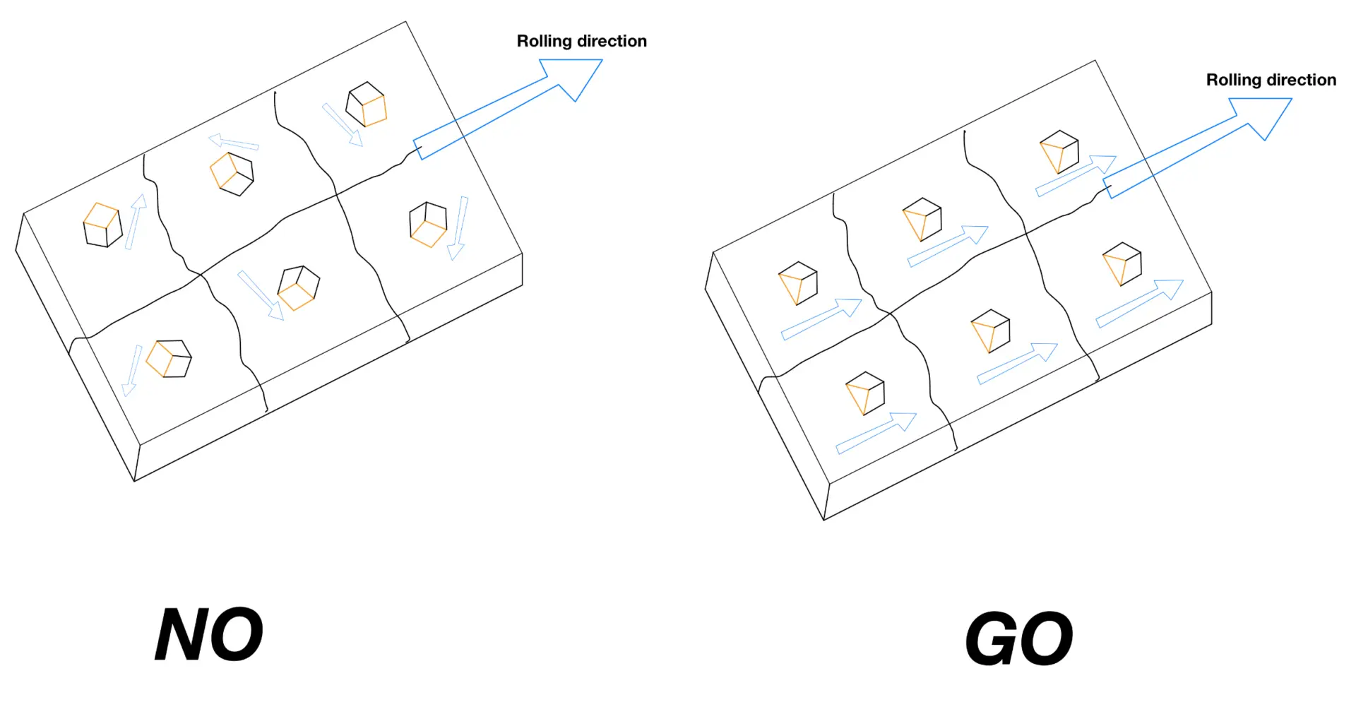
Modern electrical steels achieve core losses below 1.5 W/kg at 1.5 Tesla and 50 Hz, representing significant improvements over conventional materials. Grain-oriented electrical steels provide superior magnetic properties in specific directions, while non-oriented grades offer consistent performance regardless of magnetization direction.
Why Stator Quality Matters: Credibility in Industrial Applications
Stator construction quality directly impacts motor reliability, efficiency, and operational costs throughout the equipment lifecycle. In industrial environments, motor failures result in production losses, maintenance expenses, and safety concerns that far exceed initial equipment costs.
Manufacturing facilities typically experience motor-related downtime costs ranging from $10,000 to $50,000 per incident, making stator reliability a critical economic factor. Motors with inferior stator construction exhibit higher failure rates, increased energy consumption, and shortened service life compared to properly designed units.
Compliance with established standards such as NEMA (National Electrical Manufacturers Association) and IEC (International Electrotechnical Commission) ensures consistent performance characteristics and global compatibility. These standards specify construction requirements, testing procedures, and performance criteria that validate stator quality and reliability.
Quality stator construction incorporates precision manufacturing tolerances, proper material selection, and validated assembly processes that maintain electromagnetic performance over extended operating periods. For those seeking proven expertise and dependable stator solutions, Yucca Motor Lamination offers valuable resources and advanced manufacturing capabilities. This attention to detail translates directly into reduced maintenance costs, improved energy efficiency, and enhanced operational reliability.
Diagnosing Common Stator Failures
Stator-related failures represent the primary cause of electric motor breakdowns, making accurate diagnosis essential for effective maintenance programs. Systematic troubleshooting procedures enable technicians to identify failure modes and implement appropriate corrective actions.
Table 4: Stator Failure Troubleshooting Guide
| Symptom | Potential Cause | How to Test |
|---|---|---|
| Motor won’t start, hums loudly | Open or shorted winding | Use a multimeter to check for resistance between phases |
| Motor overheats quickly | Winding insulation failure | Perform an insulation resistance (megohmmeter) test |
| Breaker trips on startup | Phase-to-ground short | Check for continuity between windings and the stator frame |
Winding failures typically manifest as open circuits, short circuits between phases, or ground faults to the stator frame. Open winding failures prevent current flow and eliminate torque production, while short circuits create excessive current draw and rapid overheating.
Insulation degradation occurs gradually through thermal cycling, contamination, or mechanical stress. Regular insulation resistance testing using megohmmeter equipment provides early warning of developing problems before catastrophic failure occurs.
Core damage results from manufacturing defects, mechanical stress, or overheating conditions that compromise lamination bonding or create localized hot spots. Visual inspection and core loss testing identify these issues before they cause winding damage.
Preventive maintenance programs incorporating regular electrical testing, thermal imaging, and vibration analysis detect developing stator problems while corrective action remains cost-effective. Early detection typically reduces repair costs by 60-80% compared to run-to-failure scenarios.
Frequently Asked Questions (FAQ) about Electric Motor Stators
1. Can an electric motor stator be repaired?
Stator repair is technically feasible through rewinding processes that replace damaged conductors and insulation systems. However, economic considerations favor replacement over repair for smaller motors due to labor costs and reliability concerns. Large industrial motors with custom specifications often justify rewinding expenses when performed by qualified service centers.
2. What happens when a stator goes bad?
Stator failures produce various symptoms depending on the specific failure mode. Complete winding failures prevent motor starting, while partial failures cause overheating, reduced torque output, excessive vibration, and inconsistent speed regulation. Continued operation with a damaged stator typically leads to secondary damage and increased repair costs.
3. What is the difference between a stator and an alternator?
The stator represents a component within an alternator assembly, while the alternator constitutes the complete electromagnetic generator unit. Alternators contain both stator and rotor assemblies along with mechanical components, cooling systems, and electrical connections necessary for AC power generation.
4. How long does a stator last?
High-quality stators in properly maintained motors typically provide 15-25 years of reliable service under normal operating conditions. Service life depends primarily on operating temperature, environmental conditions, load cycling, and maintenance practices. Excessive heat represents the primary factor limiting stator longevity through insulation degradation.
The Foundation That Powers Modern Industry
Electric motor stators serve as the electromagnetic foundation that enables precise control of mechanical power in countless applications. Their construction quality, material selection, and maintenance directly influence motor reliability, energy efficiency, and operational costs throughout extended service life.
Understanding stator design principles, failure modes, and diagnostic techniques empowers engineers and technicians to optimize motor performance while minimizing unplanned downtime. As industrial automation continues expanding, the critical role of high-quality stators in maintaining productive operations becomes increasingly apparent.
The rotor may capture attention through its visible motion, but the stator remains the silent, stationary component that transforms electrical energy into the controlled magnetic fields powering modern industry.