The rotor is the rotating heart of every electric motor — the component that converts electromagnetic energy into mechanical torque. Whether you are designing a fractional-horsepower servo drive or specifying a multi-megawatt generator, the rotor’s type, material, and construction define the motor’s efficiency, power density, speed capability, and long-term reliability.
This guide is built for engineers, procurement managers, and technical decision-makers who need a comprehensive reference on rotor fundamentals. We cover every major rotor topology used in modern AC and DC machines, the electrical steel grades and lamination designs that determine core performance, the manufacturing processes that turn raw steel coil into finished rotor stacks, and the engineering trade-offs that shape every design decision. Where relevant, we draw on our experience at Yucore Technologies as a motor lamination and electrical steel specialist serving OEMs across the electric motor industry.
Table of Contents
What Is an Electric Motor Rotor?
A rotor is the rotating assembly inside an electric motor that interacts with the stator’s magnetic field to produce torque. In most motor configurations, the rotor sits inside the stator (inner rotor), though outer-rotor designs exist for specific applications like ceiling fans and in-wheel EV motors.
The rotor serves three fundamental functions in the motor’s electromagnetic circuit. First, it provides the torque output — converting electromagnetic forces into rotational mechanical energy delivered through the shaft. Second, it completes the magnetic flux path, providing a low-reluctance return path for the magnetic flux generated by the stator windings or permanent magnets. Third, depending on the motor type, the rotor participates in speed regulation — either by maintaining synchronous lock with the stator field (synchronous machines) or by operating at a controlled slip (induction machines).
Rotor vs. Stator — Roles in the Motor Assembly
The rotor and stator are complementary halves of the motor’s magnetic circuit. Understanding their distinct roles clarifies why each component has different material, thermal, and mechanical requirements.
| Parameter | Rotor | Stator |
|---|---|---|
| Position | Rotates (inner, in most configurations) | Stationary (outer housing-mounted) |
| Primary function | Torque output and energy conversion | Magnetic field generation and flux guidance |
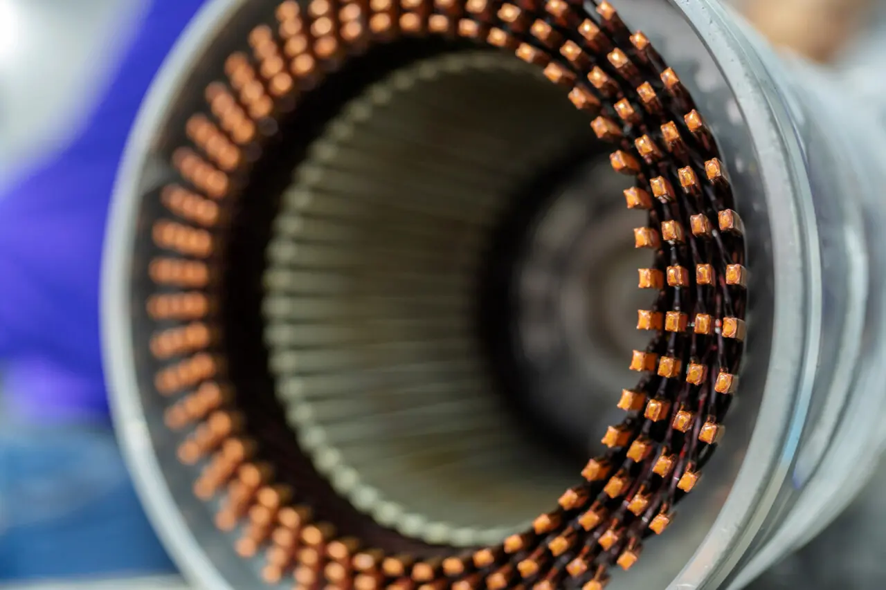
| Winding type (AC induction) | Squirrel cage bars or wound coils | Distributed copper windings in slots |
| Core material | Laminated non-oriented electrical steel | Laminated non-oriented electrical steel |
| Thermal challenge | Heat dissipation limited by rotation and air gap | Easier cooling access via housing contact |
| Mechanical stress | Centrifugal forces increase with the square of speed | Primarily static structural loads |
Types of Electric Motor Rotors
Rotor classification follows motor type and construction method. The choice of rotor topology is ultimately driven by the application’s requirements — torque profile, speed range, efficiency targets, production volume, and cost. No single rotor type is universally superior; each represents a set of engineering trade-offs.
Squirrel Cage Rotor
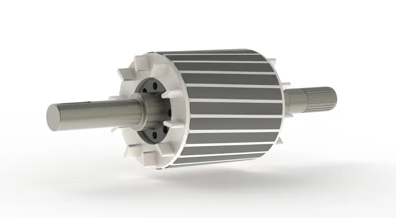
The squirrel cage rotor is the workhorse of industrial electric motors. Its construction consists of a laminated electrical steel core with conductive bars — typically die-cast aluminum or, in premium-efficiency designs, fabricated copper — inserted into rotor slots and short-circuited at both ends by end rings. The name comes from the cage-like structure formed by the bars and rings.
The operating principle is straightforward: the rotating magnetic field from the stator induces currents in the rotor bars via electromagnetic induction. These induced currents interact with the stator field to produce torque. The rotor always turns slightly slower than the synchronous speed of the stator field — this speed difference is called slip, and it is essential for current induction.
Squirrel cage rotors dominate general industrial applications because they are mechanically rugged, require virtually no maintenance (no brushes, slip rings, or rotor windings to service), and are the lowest-cost rotor type to manufacture at scale. A typical application is a NEMA-frame squirrel cage motor driving a 50 HP industrial fan or centrifugal pump — an environment where reliability and low maintenance outweigh the need for precise speed control.
Wound Rotor
The wound rotor replaces the squirrel cage bars with insulated copper windings that are connected to external circuits through slip rings and brushes mounted on the shaft. This construction allows operators to insert external resistance into the rotor circuit, which modifies the motor’s speed-torque characteristics.
By adjusting rotor resistance, wound rotor motors can deliver high starting torque at reduced starting current — a critical advantage for heavy-inertia loads. The trade-off is increased mechanical complexity, higher maintenance requirements (slip rings and brushes wear over time), and lower efficiency at reduced speeds compared to VFD-driven squirrel cage motors.
Wound rotor motors remain the preferred choice for specific heavy-duty applications such as overhead cranes, mine hoists, and large conveyors where controlled acceleration under extreme load is a non-negotiable requirement. For example, a wound rotor motor driving a mining conveyor can provide smooth, controlled acceleration of a fully loaded belt that may carry hundreds of tons of material.
Permanent Magnet Rotor (PM)
Permanent magnet rotors use high-energy-density magnets — most commonly neodymium iron boron (NdFeB) rare-earth magnets, or lower-cost ferrite magnets — to generate the rotor’s magnetic field without any electrical excitation. This eliminates rotor copper losses entirely, which is the primary reason PM motors achieve the highest efficiencies among common motor types.
PM rotors come in two principal configurations. Surface-mounted permanent magnet (SPM) rotors bond or mechanically retain magnets on the rotor’s outer surface. Interior permanent magnet (IPM) rotors embed the magnets inside pockets within the lamination stack. The IPM configuration has become dominant in high-performance applications because it enables exploitation of reluctance torque in addition to magnet torque, provides inherent magnet retention against centrifugal forces, and allows effective field weakening for wide-speed-range operation.
The EV traction motor market is overwhelmingly IPM. Automakers favor this topology because it delivers the combination of high power density, high efficiency across the drive cycle, and a wide constant-power speed range that battery electric vehicles demand. A modern EV traction motor typically uses an IPM rotor with NdFeB magnets, 0.25–0.35 mm laminations, and a maximum speed of 12,000–20,000 RPM.
Salient Pole Rotor
Salient pole rotors feature protruding pole structures with concentrated field windings wrapped around each pole. The field windings are excited with direct current, supplied either through slip rings and brushes or through a brushless exciter mounted on the same shaft.
This rotor type is purpose-built for low-speed, high-pole-count synchronous machines. The protruding pole geometry accommodates the large number of poles (often 10–60+) needed to achieve synchronous speed at low rotational velocities. The non-uniform air gap created by the salient poles is a defining characteristic — it produces reluctance torque in addition to the excitation torque from the field windings.
The classic application is the hydroelectric generator, where a salient pole rotor with 20–40+ poles operates at speeds as low as 75–200 RPM, directly coupled to a water turbine. Large low-speed synchronous motors used in cement mills and ball mills also use salient pole rotors.
Salient pole geometry also appears at smaller scales in stepper motors, which represent one of the most pronounced applications of this configuration. In a hybrid stepper motor, both the stator and rotor feature salient pole structures. The stator has concentrated copper windings wrapped around each protruding pole, while the rotor consists of two finely toothed caps made from stacked electrical steel laminations, sandwiching a permanent magnet disc between them. Unlike the cast aluminum or cast copper conductor cages found in squirrel cage induction motor rotors, stepper motor rotors contain no conductive cage structure — torque is produced through reluctance variation and permanent magnet interaction rather than induced rotor currents.
The toothed salient geometry creates discrete preferential alignment positions, enabling the characteristic step-by-step rotation (typically 1.8° per step, or 200 steps per revolution in hybrid designs). This deliberate cogging effect — which would be undesirable in a continuous-rotation synchronous generator — is precisely the feature that makes steppers valuable for precision positioning applications.
Cylindrical (Non-Salient) Rotor
Cylindrical rotors — also called round rotors or non-salient pole rotors — feature a smooth, uniform outer surface with distributed field windings placed in slots machined into a solid forged steel cylinder (or, less commonly, a laminated core). The uniform air gap produces smooth torque and low mechanical vibration at high rotational speeds.
This rotor type is designed exclusively for high-speed, low-pole-count (typically 2-pole or 4-pole) synchronous generators driven by steam or gas turbines. The solid forged construction withstands the extreme centrifugal stresses at speeds of 3,000 RPM (50 Hz systems) or 3,600 RPM (60 Hz systems). A 2-pole cylindrical rotor in a natural gas combined-cycle turbine generator operating at 3,600 RPM is a standard configuration in modern power generation.
Reluctance Rotor (Synchronous Reluctance & Switched Reluctance)
Reluctance rotors produce torque through the rotor’s tendency to align itself with the path of minimum magnetic reluctance — no magnets and no rotor windings are required. This makes them the simplest and most robust rotor constructions available.
Synchronous reluctance (SynRM) rotors use a laminated steel stack with carefully designed internal flux barriers (air gaps cut into the laminations) that create a high saliency ratio — a large difference in magnetic reluctance between the direct and quadrature axes. SynRM motors are gaining significant traction as IE5 ultra-premium efficiency alternatives to induction motors in industrial pump and fan applications, as defined by the IEC 60034-30 standard framework.
Switched reluctance (SRM) rotors use a doubly salient geometry — both the stator and rotor have protruding poles. SRMs are mechanically the simplest motors, but they require sophisticated power electronic control and historically have suffered from higher torque ripple and acoustic noise. Applications include aerospace actuators and specific industrial drives where extreme robustness and high-temperature operation are prioritized.
Rotor Type Comparison Matrix
| Rotor Type | Efficiency | Power Density | Cost | Maintenance | Speed Range | Typical Application |
|---|---|---|---|---|---|---|
| Squirrel Cage | Moderate–High | Moderate | Low | Very Low | Fixed or VFD | Industrial general purpose |
| Wound Rotor | Moderate | Moderate | Medium | Higher (slip rings/brushes) | Adjustable | Cranes, hoists, heavy conveyors |
| Permanent Magnet (IPM) | Very High | Very High | High | Very Low | Wide (with VFD) | EV traction, servo drives |
| Salient Pole | High | Low–Moderate | Medium | Moderate (brushes/exciter) | Low-speed synchronous | Hydro generators, sync motors |
| Cylindrical | High | High | High | Moderate | High-speed synchronous | Turbo generators (steam/gas) |
| SynRM | High (IE5 capable) | Moderate | Low–Medium | Very Low | VFD-dependent | Premium industrial drives |
| SRM | Moderate–High | Moderate | Low | Very Low | VFD-dependent | Aerospace, special industrial |
Rotor Core Materials and Electrical Steel Selection
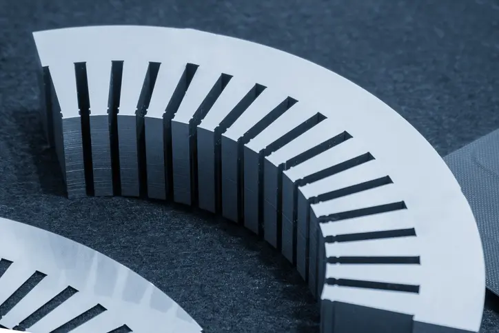
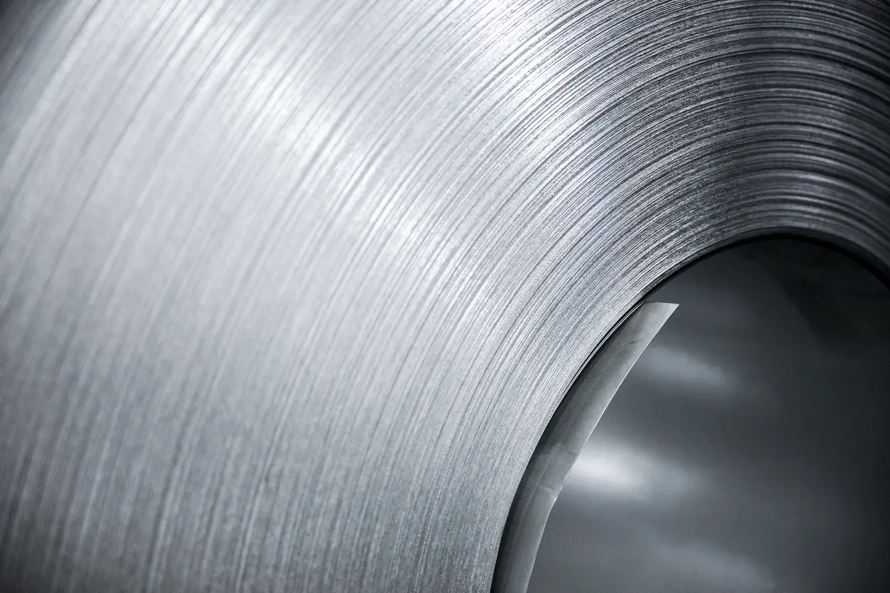
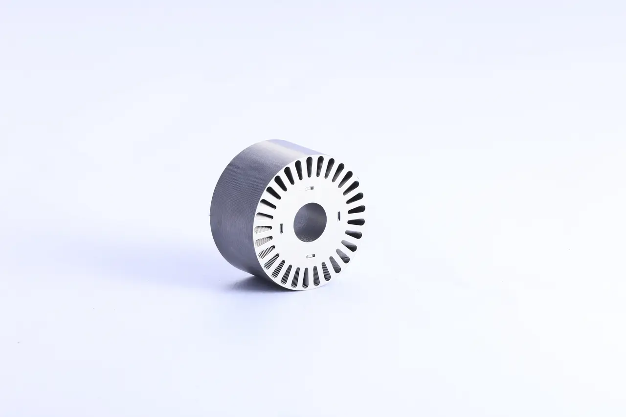
The rotor core is the magnetic backbone of the rotor assembly. Its material determines the motor’s core loss characteristics, magnetic flux-carrying capacity, and mechanical integrity at speed. In virtually all AC and permanent magnet motor types, the rotor core is constructed from stacked laminations of non-oriented electrical steel — a silicon-iron alloy specifically engineered for its magnetic properties.
The two critical material properties driving electrical steel selection for rotor applications are core loss (energy dissipated as heat in the core per cycle, measured in W/kg) and magnetic permeability (the material’s ability to conduct magnetic flux, reflected in its saturation flux density). These properties are in tension — alloying elements like silicon reduce core loss by increasing electrical resistivity, but they also reduce saturation flux density and make the steel more brittle.
Electrical Steel Grades for Rotor Laminations
Non-oriented (NO) electrical steel is the standard material for rotor laminations because rotating machines require uniform magnetic properties in all directions within the plane of the lamination. Grain-oriented (GO) steel, which has superior magnetic properties in the rolling direction, is used in transformers but is rarely suitable for rotors where the flux direction changes continuously as the rotor turns.
The key specifications that engineers evaluate when selecting an electrical steel grade for a rotor application include core loss (W/kg at a specified flux density and frequency, typically 1.5 T at 50 Hz), magnetic flux density at a standardized field strength — commonly B50, which is the flux density at H = 5,000 A/m — lamination thickness (mm), and mechanical yield strength (MPa — especially important for high-speed rotors).
| Grade | Thickness (mm) | Max Core Loss W15/50 (W/kg at 1.5 T, 50 Hz) | B50 min (T) at 5,000 A/m | Typical Rotor Application |
|---|---|---|---|---|
| M19 (AISI) / M270-35A (IEC) | 0.36 | ≤2.70 | ≥1.60 | General-purpose AC motors |
| M15 (AISI) / M250-35A (IEC) | 0.36 | ≤2.50 | ≥1.60 | Premium efficiency motors |
| 35CS250 (CSC) | 0.35 | ≤2.50 | ≥1.60 | Standard industrial motors |
| 20CS1500HF (CSC) | 0.20 | W10/400 ≤15.0* | ≥1.63 | High-speed PM motors, EV traction |
| Thin-gauge NO (0.10 mm) | 0.10 | Application-specific** | Typically ≥1.55–1.60 | Aerospace, ultra-high-speed rotors |
IEC equivalents for AISI grades are based on the CSC/IEC cross-reference (e.g., AISI M19 ≈ IEC M270-35A at 0.35 mm). Core loss and B50 values per IEC 60404-2 Epstein frame testing. Sources: CSC Electrical Steel Product Manual (2016), ASTM A677, IEC 60404-8-4.
* High-frequency grades like 20CS1500HF are specified at W10/400 (1.0 T, 400 Hz) rather than W15/50, because their primary application is at elevated electrical frequencies where the standard 50 Hz test condition is not representative of operating performance.
** Thin-gauge (0.10 mm) lamination grades are emerging specialty products with specifications that vary significantly by manufacturer. Core loss data at standard 50 Hz test conditions is not always published; these grades are typically characterized at 400 Hz and above.
A note on B50 vs. saturation flux density: Manufacturer datasheets specify B50 (flux density at H = 5,000 A/m) rather than a theoretical saturation flux density (Bsat). B50 is a practical measure of how readily the steel magnetizes at a standardized field strength — a higher B50 means the material reaches useful flux densities with less magnetizing current, which directly translates to better motor performance. For reference, the theoretical saturation polarization (Js) of Fe-Si alloys with ~3% silicon is approximately 2.0 T, decreasing with higher silicon content.
Yucore Insight: Grade selection is never a one-size-fits-all decision. We regularly work with customers who start with a standard grade like M19 or 35CS250 for cost-effective industrial motor production, then transition to thinner, lower-loss grades like 20CS1500HF when their application moves to higher speeds or demands premium efficiency. Our engineering team helps bridge the gap between the material datasheet and the real-world performance you need from the finished rotor stack.
Lamination Thickness and Its Impact on Rotor Performance
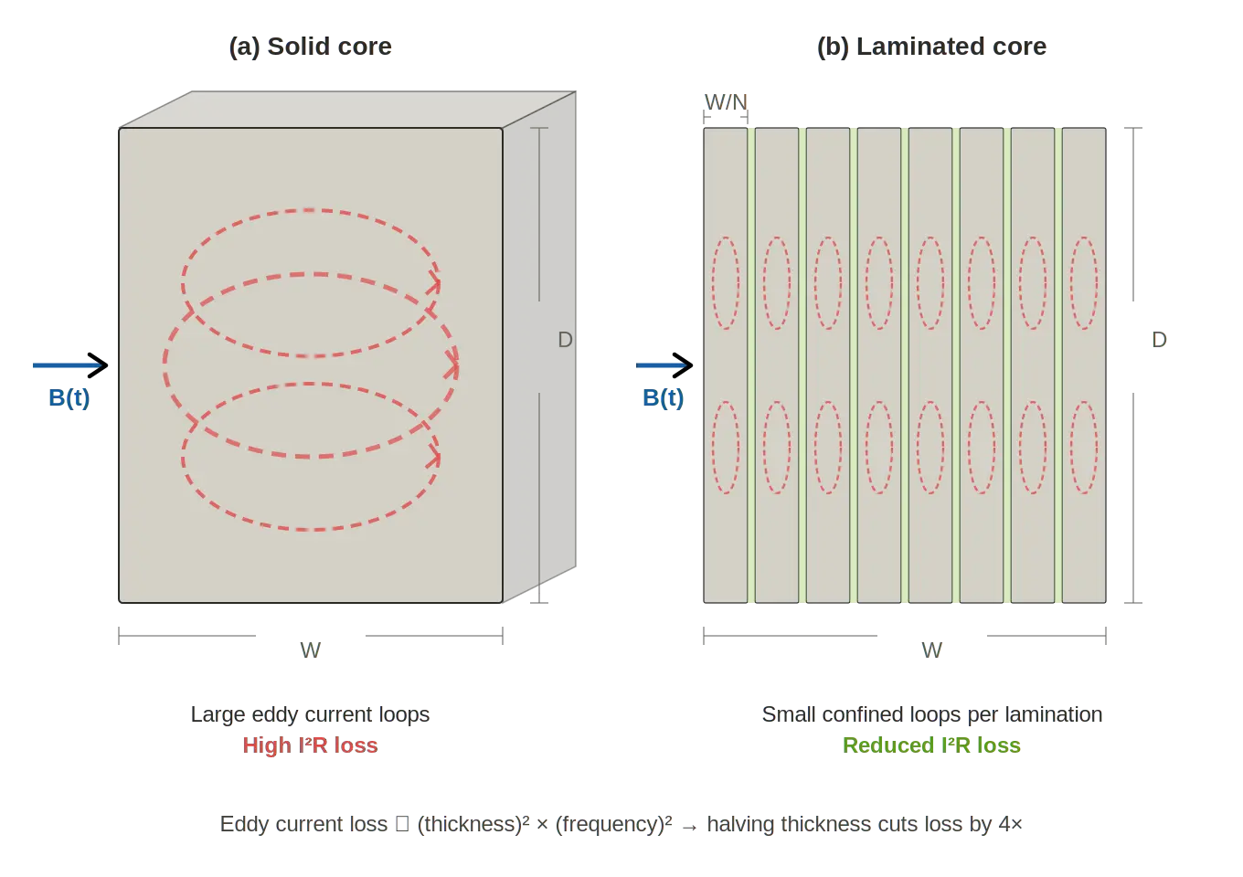
Lamination thickness is one of the most impactful — and most frequently underappreciated — design choices in rotor engineering. The fundamental physics is straightforward: eddy current losses in the core are proportional to the square of the lamination thickness and the square of the operating frequency. Thinner laminations mean lower eddy current losses, with the benefit becoming dramatically more important at higher electrical frequencies. For an in-depth analysis of how thickness affects efficiency, see our guide on motor lamination thickness and efficiency.
For a motor operating at line frequency (50 or 60 Hz), standard 0.5 mm laminations provide a well-proven balance of loss performance, manufacturing ease, and cost. But when electrical frequency rises — as it does in high-speed motors, EV traction drives, and VFD-operated industrial motors — the case for thinner laminations becomes compelling. A 4-pole IPM motor running at 15,000 RPM sees an electrical frequency of 500 Hz. At that frequency, the eddy current loss difference between 0.35 mm and 0.20 mm laminations is substantial.
The industry trend is clear: leading EV manufacturers have migrated to 0.20–0.25 mm laminations for traction motors, with next-generation designs exploring 0.10 mm for ultra-high-speed applications.
| Lamination Thickness | Eddy Current Loss | Material Cost | Stacking Complexity | Stacking Factor | Best Suited For |
|---|---|---|---|---|---|
| 0.50 mm | Higher | Lowest | Simplest | ~0.97–0.98 | Cost-sensitive, low-speed industrial |
| 0.35 mm | Moderate | Moderate | Standard | ~0.95–0.97 | General industrial |
| 0.20 mm | Low | Higher | More complex | ~0.93–0.95 | High-speed, EV traction, servo |
| 0.10 mm | Very Low | Highest | Most complex | ~0.90–0.93 | Aerospace, ultra-high-frequency |
Note: Stacking factor (the ratio of active magnetic steel to total stack volume) decreases with thinner laminations because the insulating coating between each layer occupies a proportionally larger share of the total stack height. This means the magnetic circuit designer may need to increase the stack length slightly to compensate for the reduced effective iron cross-section — a trade-off that is almost always worthwhile when the core loss reduction is significant.
Rotor Construction and Manufacturing Processes
Building a rotor core means transforming raw electrical steel sheet coil into a precisely stacked, dimensionally accurate lamination assembly. The manufacturing process chain — from coil slitting through stamping, stacking, bonding, and final balancing — determines the quality of the finished rotor just as much as the material selection does.
Stamping and Punching Rotor Laminations
Progressive die stamping is the dominant production method for rotor laminations at medium to high volumes. In this process, a strip of electrical steel feeds through a series of die stations in a single press stroke cycle. Each station performs a specific cutting operation — pilot holes first, then slot geometries, then the final outer diameter blanking — producing a finished lamination with every press stroke.
Tooling design for rotor laminations requires careful attention to the specific rotor geometry. Squirrel cage rotors need precise slot profiles to ensure consistent bar fit and electromagnetic performance. IPM rotors demand tight tolerances on magnet pocket dimensions and, critically, on the thin bridge features between the magnet pockets and the rotor OD. These bridges — typically 0.8–2.0 mm thick — must be dimensionally precise because they serve a dual role: mechanically retaining magnets against centrifugal force while remaining thin enough to saturate magnetically and limit flux leakage.
Burr control is essential. Excessive burrs on lamination edges create electrical contact between adjacent laminations in the stack, which increases eddy current losses and degrades core performance. Well-maintained progressive dies with properly ground cutting edges and appropriate clearances (typically 5–8% of material thickness per side) minimize burr height.
Laser Cutting vs. Stamping for Rotor Laminations
Laser cutting and progressive die stamping serve complementary roles in rotor lamination production. The choice between them is driven primarily by production volume, geometry complexity, and time-to-first-part requirements.
| Factor | Laser Cutting | Progressive Die Stamping |
|---|---|---|
| Volume suitability | Prototype to low-volume (up to ~5,000 units/year) | Medium to high-volume (5,000+ units/year) |
| Tooling cost | None (no die required) | High (progressive die investment) |
| Geometric flexibility | Excellent — complex IPM flux barriers, rapid design iteration | Good — limited by die geometry, changes require retooling |
| Edge quality | Heat-affected zone (HAZ) can locally degrade magnetic properties | Clean mechanical shear (with proper die maintenance) |
| Per-piece cost at volume | Higher | Significantly lower |
| Lead time for first parts | Days | Weeks to months (tooling fabrication) |
| Thin-gauge capability | Handles 0.10–0.20 mm well | Challenging below 0.20 mm — increased die wear |
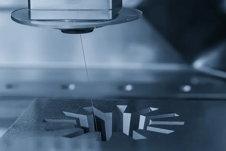
In practice, many motor development programs start with laser-cut or wire-edm-cut prototypes for design validation and electromagnetic testing, then transition to stamped production laminations once the design is frozen and volumes justify the die investment. For complex IPM rotor geometries with intricate flux barrier shapes, laser cutting may remain the preferred method even at moderate volumes due to the tooling complexity and cost that stamping would require.
Stacking, Bonding, and Assembling Rotor Cores
Once individual laminations are cut, they must be assembled into a dimensionally precise stack. Several methods are used, each with distinct trade-offs:
Interlocking (cleating): Embossed dimples on each lamination mechanically interlock with the adjacent lamination during the stacking process, often performed in-die during stamping. This is the fastest and most common method for industrial motor laminations. The trade-off is that the embossment creates a localized short circuit between laminations, slightly increasing core loss in that area.
Welding: Laser or TIG welds along the stack OD provide strong mechanical bonding. However, the weld bead creates an electrically conductive path along the stack length, increasing eddy current losses — particularly in the outer portions of the core nearest the weld.
Self-bonding (adhesive-coated steel): The electrical steel is supplied with a thermally activated adhesive coating (backlack). After stacking, the assembly is heated and compressed to cure the adhesive, bonding all laminations together without any mechanical penetration or electrical bridging. Self-bonding is increasingly favored for high-performance applications — particularly EV traction motors — because it preserves the full magnetic properties of the steel with no additional core loss from the joining method.
Yucore Insight: We have seen a clear industry shift toward self-bonding for premium applications. For our customers producing EV motor laminations, the combination of a low-loss electrical steel grade (such as 20CS1500HF at 0.20 mm) with self-bonding stacking delivers the lowest total core loss in the finished rotor/stator assembly. For standard industrial applications where cost is the primary driver, interlocking remains the pragmatic choice.
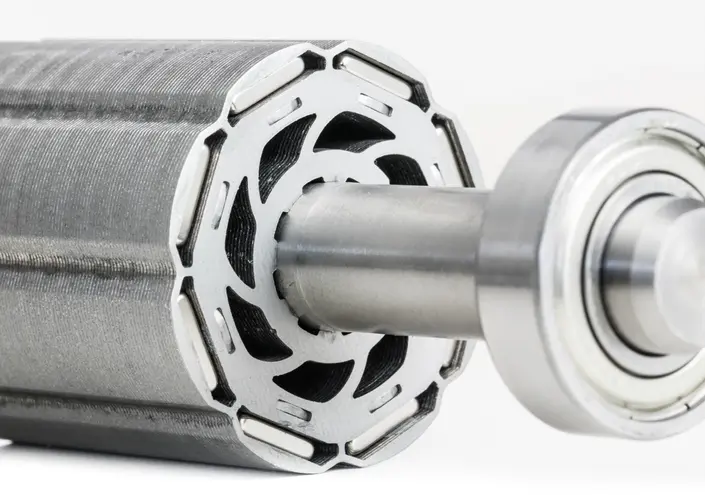
Rotor Balancing and Quality Control
A finished rotor stack must be balanced before it can be integrated into a motor assembly. Any mass imbalance in the rotor creates centrifugal forces during rotation that produce vibration, increase bearing loads, generate acoustic noise, and shorten bearing life — effects that worsen with the square of the rotational speed.
Balancing is performed in two modes. Single-plane (static) balancing corrects imbalance in one rotational plane and is sufficient for short, low-speed rotors. Two-plane (dynamic) balancing corrects imbalance in two planes simultaneously and is required for longer rotors and all high-speed applications. Material is typically removed by drilling small holes in the end laminations or, for cast rotors, by milling material from the end rings.
Beyond balancing, quality control on finished rotor stacks typically includes dimensional inspection of ID/OD concentricity and stack height, verification of slot geometry and magnet pocket dimensions (for IPM rotors), core loss testing on the finished stack (comparing measured losses against the expected losses to verify that manufacturing processes is within the accepted range), and insulation resistance testing between laminations.
Rotor Design Fundamentals — Engineering Considerations
Designing a rotor involves balancing multiple interdependent parameters. Changes to one parameter invariably affect others — increasing rotor diameter boosts torque but raises inertia and centrifugal stress; reducing the air gap improves flux linkage but tightens manufacturing tolerances. The engineer’s task is to find the combination that best serves the application’s requirements within its constraints.
Air Gap and Its Effect on Motor Performance
The air gap — the narrow radial clearance between the rotor’s outer surface and the stator’s inner bore — is one of the most critical dimensions in any electric motor. Typical air gap values range from about 0.2 mm in small fractional-horsepower motors to 2.0 mm or more in large industrial machines, though the exact value depends on motor type, size, and speed.
A smaller air gap increases the magnetic flux linkage between stator and rotor, which improves torque production and power factor. However, smaller air gaps demand tighter mechanical tolerances on rotor and stator concentricity, increase the risk of rotor-to-stator contact due to thermal expansion or bearing wear, and can amplify parasitic effects like slot harmonics and unbalanced magnetic pull.
Air gap uniformity — which depends directly on the concentricity and roundness of the rotor lamination stack — is just as important as the absolute air gap dimension. A non-uniform air gap creates unbalanced magnetic pull that loads bearings unevenly, generates vibration, and can produce audible noise at specific frequencies.
Rotor Slot Geometry and Electromagnetic Performance
In squirrel cage and wound rotor motors, the shape, size, and number of rotor slots directly influence the motor’s electromagnetic performance. Slot shape affects the distribution of rotor current and, consequently, the motor’s torque-speed curve, starting torque, harmonic content, and torque ripple.
Rotor slots may be open, semi-closed, or fully closed. Closed rotor slots (where the bar is completely enclosed by steel) are common in squirrel cage rotors and reduce flux pulsation harmonics, but the thin steel bridge over the slot saturates during operation — a designed-in effect that allows flux to penetrate the bar while providing mechanical retention of the conductor.
Skewing — angling the rotor slots (or, in PM motors, the magnets) relative to the axial direction — is a widely used technique to reduce cogging torque and electromagnetic noise. A typical skew is one stator slot pitch over the stack length. The trade-off is a modest reduction in the fundamental torque component, typically 1–3%, because the skew introduces a phase offset in the EMF along the stack length.
Thermal Management of the Rotor
Heat management in the rotor is inherently more challenging than in the stator because the rotor is a rotating component with limited direct access to external cooling.
Heat sources in the rotor vary by motor type. In induction motors, rotor bar losses (I²R losses in the squirrel cage) are the dominant heat source at high slip. In PM motors, rotor iron losses (eddy currents and hysteresis in the lamination stack) dominate — there are no rotor conductor losses, but the alternating flux components from stator slot harmonics and inverter switching harmonics generate measurable core heating. In all motor types, friction and windage losses contribute at higher speeds.
Design approaches to manage rotor temperature include internal cooling channels within the shaft or rotor core, rotor geometry optimization to promote air circulation through ventilation ducts cast into the core, shaft-mounted fans (in self-ventilated designs), and careful selection of lamination materials and insulation systems rated for the expected temperature class (typically Class F at 155°C or Class H at 180°C per IEC 60085).
Mechanical Stress and Speed Limits
At high rotational speeds, centrifugal forces on rotor components become a primary design constraint. The centrifugal stress on a rotating ring is proportional to the material density, the square of the peripheral velocity, and the radius — meaning stress increases rapidly as speed climbs.
For IPM rotors, the thin lamination bridges between magnet pockets and the rotor OD are the critical stress points. These bridges must be thick enough to withstand centrifugal forces at maximum speed (with a safety margin), but thin enough to saturate magnetically and limit flux leakage. Bridge thickness is calculated against the electrical steel’s yield strength — typically 300–450 MPa for standard grades, and up to 500+ MPa for high-strength grades designed for high-speed applications.
Surface-mounted PM rotors face an even more direct challenge: the magnets themselves must be retained against centrifugal force. At speeds above roughly 6,000–8,000 RPM, adhesive bonding alone is often insufficient, and designers add a high-strength non-magnetic retention sleeve (typically Inconel or carbon fiber composite) around the rotor OD.
Key Rotor Design Parameters and Trade-offs
| Design Parameter | Effect of Increase | Trade-off |
|---|---|---|
| Air gap length | Lower flux density, lower torque per amp | Easier manufacturing tolerance, reduced UMP risk |
| Rotor diameter | Higher torque (longer moment arm) | Higher rotational inertia, higher centrifugal stress |
| Stack length | Higher torque, higher output power | Longer motor package, higher material cost |
| Rotor slot count | Smoother torque, lower harmonic content | More complex stamping die, higher tooling cost |
| Lamination thickness (thinner) | Lower core loss at high electrical frequency | Higher material cost, lower stacking factor, tooling challenges |
| Skew angle | Lower cogging torque, reduced noise | Slight reduction in average torque (typically 1–3%) |
| IPM bridge thickness | Higher mechanical strength at speed | Increased magnetic flux leakage across bridge |
Rotor Applications Across Industries
Rotor type and design choices are ultimately dictated by the performance requirements of the target application. Here is how the primary industries select and optimize their rotor assemblies.
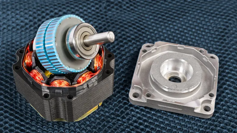
Electric Vehicles (EV)
The EV traction motor is arguably the most demanding application for rotor design today. The dominant rotor type is the interior permanent magnet (IPM), which accounts for the vast majority of production EV traction motors worldwide.
Key requirements include high power density (typically 3–6 kW/kg at the motor level), high efficiency across the entire drive cycle (not just at one rated point), a wide speed range from near-zero to 12,000–20,000 RPM, and the ability to deliver peak torque on demand within milliseconds. These requirements drive the use of NdFeB rare-earth magnets, thin-gauge (0.20–0.27 mm) low-loss electrical steel laminations, and sophisticated IPM flux barrier geometries optimized through finite-element electromagnetic and structural simulations.
Example: A compact EV traction motor might use an 8-pole IPM rotor with V-shaped magnet pockets, 0.20 mm lamination stacks bonded via self-bonding adhesive coating, and a maximum operating speed of 16,000 RPM. At that speed, the electrical frequency reaches approximately 1,067 Hz — underscoring why thin-gauge, low-loss laminations are not optional but essential.
Industrial Motors and Drives
Industrial motors represent the largest volume segment for rotor lamination production. The squirrel cage rotor dominates for general-purpose applications — fans, pumps, compressors, and conveyor drives — where reliability, low maintenance, and cost-effectiveness are the primary selection criteria.
The global push toward higher motor efficiency standards (IEC 60034-30-1 defines classes IE1 through IE4 for line-operated motors, with IE5 defined under IEC 60034-30-2 for variable-speed motors) is driving material upgrades in industrial rotor cores. Meeting IE3 (Premium Efficiency) or IE4 (Super Premium Efficiency) often requires moving to lower-loss electrical steel grades, optimizing rotor slot design, and reducing manufacturing-induced losses. SynRM technology — which uses a magnet-free reluctance rotor with VFD control — is emerging as a pathway to IE5 (Ultra Premium Efficiency) in pump and fan applications.
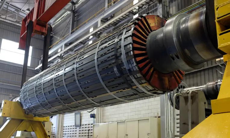
Power Generation
Generator rotors are among the largest and most mechanically demanding rotors manufactured. Hydroelectric generators use salient pole rotors with pole counts ranging from 10 to 60+ poles, operating at low speeds (75–600 RPM) directly coupled to water turbines. These rotors must be mechanically robust enough to withstand decades of continuous operation with minimal maintenance.
Thermal power generation (steam and gas turbine-driven generators) uses cylindrical rotors operating at 3,000 or 3,600 RPM. These rotors are typically forged from a single billet of high-strength steel to withstand the extreme centrifugal stresses at high speed, and the field windings are placed in machined slots.
Aerospace and Defense
Aerospace represents the leading edge of rotor material and design technology. More-electric aircraft architectures, UAV propulsion systems, and satellite reaction wheels demand rotors with ultra-high power-to-weight ratios and the ability to operate at very high speeds (10,000–100,000+ RPM for some micro-turbine generator applications).
These requirements push toward the thinnest available lamination gauges (0.10 mm and below), high-strength electrical steel alloys, and advanced rotor topologies. Iron-cobalt alloys (such as Hiperco/Vacoflux), which offer saturation flux densities of approximately 2.35 T — significantly higher than the ~2.0 T of standard silicon steel — find applications here where performance justifies the substantially higher material cost.
Rotor Type by Industry Application
| Industry | Typical Rotor Type | Key Priority | Typical Speed Range |
|---|---|---|---|
| Electric Vehicles | IPM (Interior Permanent Magnet) | Efficiency + power density | 0–20,000 RPM |
| Industrial (General Purpose) | Squirrel Cage Induction | Reliability + cost | 1,000–3,600 RPM |
| Industrial (Premium Efficiency) | SynRM or PM-assisted SynRM | IE4/IE5 efficiency | 1,000–3,600 RPM (VFD) |
| Hydroelectric Generation | Salient Pole Synchronous | Low-speed torque, longevity | 75–600 RPM |
| Thermal Power Generation | Cylindrical Synchronous | High-speed mechanical stability | 3,000–3,600 RPM |
| Aerospace & Defense | PM (SPM or IPM) / SRM | Power-to-weight ratio | 10,000–100,000+ RPM |
Frequently Asked Questions (FAQ)
What is the difference between a rotor and a stator?
The rotor is the rotating component of an electric motor; the stator is the stationary component. The stator generates a magnetic field (via windings or magnets); the rotor interacts with that field to produce rotational torque. Both typically use laminated electrical steel cores, but they face different mechanical and thermal challenges — the rotor contends with centrifugal forces and limited cooling access, while the stator manages higher winding temperatures but benefits from direct contact with the motor housing for heat dissipation.
What material is used in rotor cores?
The vast majority of rotor cores are built from laminated non-oriented (NO) electrical steel — a silicon-iron alloy with silicon content typically ranging from 1% to 3.5%. Common grades include M19 (AISI designation), 35CS250, and thinner high-frequency grades like 20CS1500HF. The steel is laminated (stacked in thin sheets with insulating coating between layers) to minimize eddy current losses.
Why are rotor cores laminated?
Lamination reduces eddy current losses. When a solid steel core is exposed to a changing magnetic field, circulating currents (eddy currents) are induced within the steel, generating waste heat. Slicing the core into thin, electrically insulated sheets confines these currents to each individual lamination, drastically reducing the total eddy current path length and the associated power loss. This effect follows directly from Faraday’s law of electromagnetic induction — the thinner the lamination, the smaller the induced voltage driving the eddy current loop, and the lower the resulting loss.
What is the most efficient rotor type?
In terms of motor efficiency, the interior permanent magnet (IPM) rotor generally achieves the highest efficiency across the broadest operating range. This is because the permanent magnets provide the rotor’s magnetic field without any electrical power input, eliminating rotor conductor losses entirely. However, “most efficient” is context-dependent — a SynRM rotor can approach IPM-level efficiency in fixed-speed pump applications without the cost of rare-earth magnets, and a well-designed squirrel cage rotor can meet IE3/IE4 efficiency levels for general-purpose duty.
How does rotor design affect motor efficiency?
Rotor design affects efficiency through multiple channels: the electrical steel grade and lamination thickness determine core loss; slot geometry and conductor design affect rotor copper loss and harmonic losses; air gap dimensions influence magnetizing current requirements; and manufacturing quality (burr height, stack alignment, balancing precision) can either preserve or degrade the efficiency that was designed on paper. In practice, moving from a 0.35 mm to a 0.20 mm lamination in a high-speed motor can reduce rotor core losses by 40% or more.
What rotor type is used in electric vehicles?
Interior permanent magnet (IPM) rotors dominate the EV traction motor market. The IPM configuration is preferred because it combines high torque density, high efficiency, a wide constant-power speed range (essential for EVs, which operate from standstill to highway speeds without a multi-speed transmission in most designs), and inherent magnet retention at high speeds. NdFeB rare-earth magnets and thin-gauge (0.20–0.27 mm) low-loss electrical steel laminations are standard in current-generation EV IPM rotors.
What is rotor skewing and why is it used?
Rotor skewing means angling the rotor slots (or magnets) relative to the stator slots, typically by one stator slot pitch over the stack length. The purpose is to reduce cogging torque — the pulsating torque caused by the interaction between the rotor and stator slot openings as they pass each other — and to reduce electromagnetic noise. The trade-off is a small reduction in the motor’s average torque output, typically 1–3%, because the skew introduces a slight phase offset in the back-EMF waveform along the rotor’s axial length.
How are rotor laminations manufactured?
Rotor laminations are manufactured primarily by two methods. Progressive die stamping is the standard for medium- to high-volume production: a coil of electrical steel feeds through a multi-station die that punches the complete lamination geometry in each press stroke. Laser cutting is used for prototyping, low-volume production, and complex geometries (such as IPM flux barriers) where die tooling would be prohibitively expensive or inflexible. After cutting, laminations are stacked and bonded using interlocking, welding, or self-bonding adhesive methods.