Table of Contents
Introduction
From an iron core loss standpoint, even a meticulously modeled finite‑element analysis (FEA) can diverge from real‑world measurements, frustrating engineers and suppliers alike. Four often‑overlooked manufacturing realities fuel this gap: (1) stamping and punching burrs that concentrate flux at sharp edges, (2) mechanical interlocking tabs that distort local magnetic paths, (3) welding heat‑affected zones that alter electrical resistivity, and (4) press‑fit forces from the motor housing that squeeze laminations and raise eddy‑current density. When these factors are not mirrored in the simulation, predicted efficiency looks optimistic while measured core loss climbs, forcing additional prototyping loops. Each extra design cycle inflates development cost and delays product launch—painful consequences that can be mitigated through more faithful stack‑level modeling and process control.
Watch Our Overview in 49s!
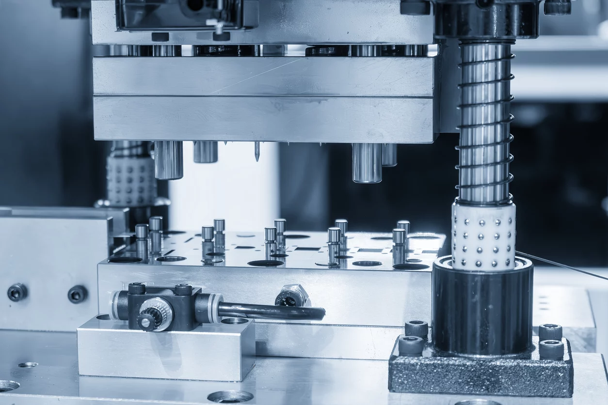
1. Stamping / Punching Burring Effects on the Edges to Core Loss
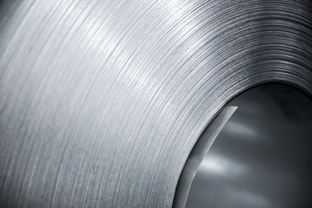
Stamping is a high‑speed, high‑load shearing process; the severe plastic deformation at the cut edge deforms grains and elevates the dislocation density, introduces residual stress. This damaged “shear zone” (typically 200–400 µm wide) increases local coercivity, so every flux reversal consumes extra hysteresis energy. Experiments on non‑oriented 50WW800 steel show a hardened layer and sharp rise in power loss right at the punched edge, confirming the link between crystal‑structure degradation and higher core loss (ResearchGate).
Even more critically, protruding burrs can short adjacent laminations: when two sheets are bridged on both sides, a closed path forms for inter‑laminar eddy currents, sending eddy‑current and total core loss soaring beyond FEA predictions (ORCA). However, just to mention that protruding burrs are vital mistakes and are usually well-handled by trustworthy lamination suppliers.
Tool condition amplifies the problem. As the punch and die wear, clearance grows and cutting becomes less clean, driving burr height up and broadening the plastically damaged rim. A recent manufacturing review notes that blunt tooling and the resulting burrs are “two major disadvantages” of high‑volume punching, directly eroding stacking factor and inflating core loss in finished motors (MDPI). Without incorporating edge‑quality degradation in the material model, FEA underestimates both hysteresis and eddy‑current components, forcing costly redesign loops or additional post‑processing (e.g., stress‑relief anneal, edge grinding) to bring measurements back in line.
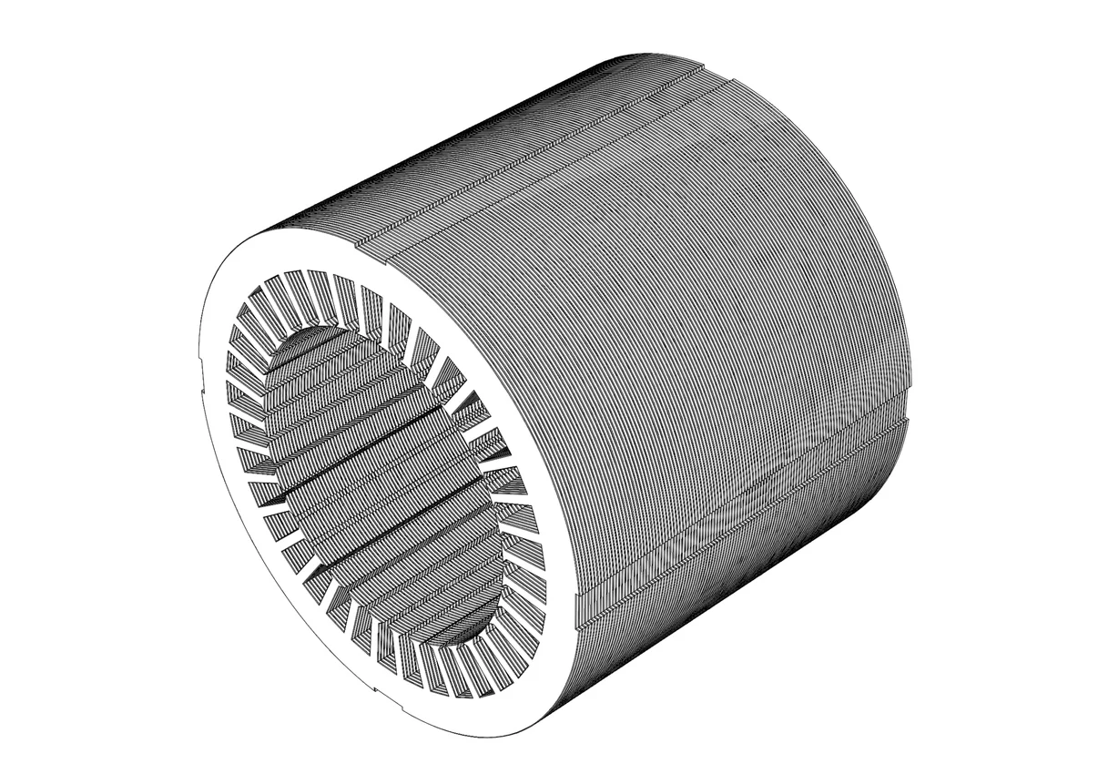
2. Interlocking Between the Stack Lamination Sheets Effects on Core Loss
Progressive‑die stamping forms small rectangular or V‑shaped interlocking tabs that clinch one lamination to the next and remove the need for external fasteners. The punch crushes insulation, plastically strains the steel, and electrically bridges adjacent sheets. Because most finite‑element preprocessors assume perfectly insulated layers, these conductive bridges are rarely represented. The omission looks harmless on‑screen, yet the affected region sits directly in the main flux path, so even a few tabs can swing core loss predictions well below reality.
Empirical data confirm the effect. Lamprecht et al. measured an 8 % rise in 50 Hz eddy‑current loss for a single interlock in 0.35 mm NOES, with loss increasing linearly as more tabs were added (PMC). A recent Energies review echoed the trend, showing iron loss climbing with interlock density and stressing that radial tabs were most detrimental( MDPI). When the same geometry was simulated without tabs, the calculated core loss fell short of measurement by up to 15 %, exposing a blind spot in many design workflows.
For high‑speed drives that operate deep into the kilohertz range, those hidden bridges can exceed statutory efficiency limits. Accounting for tab conductivity—or adopting adhesive Self-bonding—keeps model and measured core loss aligned and averts costly redesign cycles.


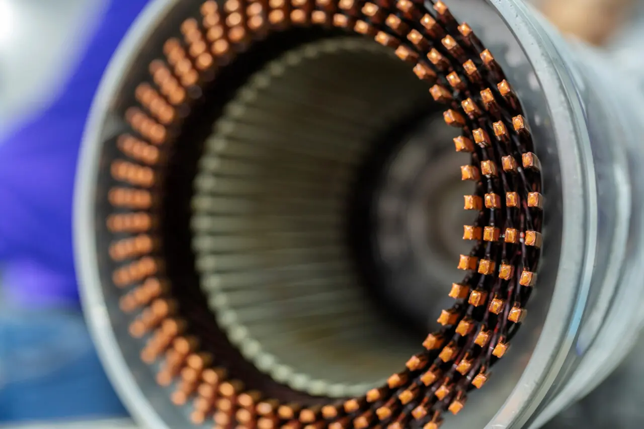
3. Welding of the Stack Lamination Sheets Effects on Core Loss
Fusion, laser or resistance welding is widely used to hold stator laminations together, but the molten path produces a heat‑affected zone where grain size coarsens and electrical resistivity drops. IEEE tests on welded 0.35 mm NOES report up to a 12 % rise in specific core loss because the altered microstructure raises local hysteresis and allows higher eddy‑current density (ResearchGate). A 2023 review in Energies adds that such metallurgical changes are invisible to Epstein strips, so designers who rely only on catalogue data could severely under‑predict stack‑level core loss once welds are introduced( MDPI).
Beyond material degradation, the continuous weld bead electrically bridges dozens of sheets, creating a low‑impedance ring that circumvents the inter‑laminar insulation. Under alternating flux, circulating currents concentrate around the weld, generating localized hot spots and inflating the eddy‑current component of total core loss far above FEA baselines that omit conductive paths (Aalto University’s research portal). The slightly imbalance and rigidity of the bead can also shift the core’s dynamic balance, intensifying magnetostrsiction-driven vibration and audible noise, especially in high‑speed traction drives. Mitigation options include switching to adhesive self-bonding method, or explicitly modeling the weld conductivity within the finite‑element solver to avoid expensive redesign loops.
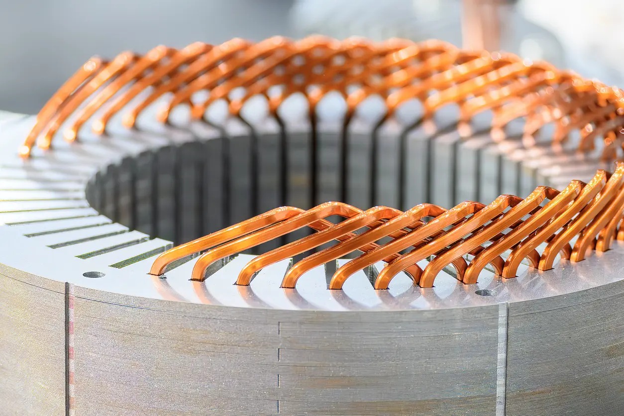
4. Press-Fit Forces From the Motor Housing Effects on Core Loss
During assembly, many stators are press‑fit or shrink‑fit into an aluminium or steel housing. The slight interference generates radial compressive stress—peaking at the outer rim of the back‑yoke—where magnetic flux density is already high. Laboratory and simulation studies agree that this stress degrades permeability, widens hysteresis loops and thus elevates core loss locally and globally. A JMAG application note reports about a 10 % rise in iron‑loss density when press‑fit stress is included, with the hottest spots concentrated exactly at the outer circumference(jmag-international.com).
More recent IECON‑2024 measurements on a 100 kVA synchronous generator showed that neglecting stacking force in FEA underestimated total core loss by roughly 12 % (ResearchGate). Likewise, an IEEE Energy‑Conversion study comparing several manufacturing steps found compressive shrink‑fit stress alone added up to 10 – 20 % extra loss relative to a free stack (Aalto University’s research portal).
Because most electromagnetic solvers ignore mechanical stress unless the designer couples a structural field, simulations predict an overly optimistic efficiency. Incorporating stress‑dependent B‑H curves or applying a magneto‑mechanical coupling closes that gap and avoids late‑stage surprises in thermal rise, noise, and power‑rating derating.
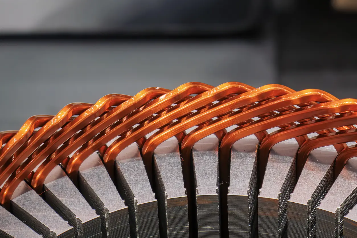
Aiming for Lower Core Loss? Go for Self-Bonding Technique
Switching from mechanical interlocks or weld method to a self‑bonding (back-adhesive) insulation transforms the stack into a seamless composite: thin adhesive layers on each lamination activate under heat, flow, and cure, locking the motor core without any rivets, interlocking points, or fusion zones. By removing those conductive bridges, our internal magnetic properties tester tests on 0.5 mm stators have shown up to a 30 % drop in measured core loss at 50, 200, and 400 Hz compared with an otherwise identical interlocking-method build. Results naturally vary with geometry, material grade, and duty cycle, so treat that figure as a ball‑park rather than an iron‑clad guarantee.
Just as important, the adhesive self-bonding solution erases two of the four discrepancy drivers outlined above. No weld path means no heat‑affected microstructure, and no interlocking tabs means no unexpected eddy‑current loops—streamlining both FEA modeling and root‑cause analysis. For design teams chasing every watt of efficiency, self‑bonding offers a clean, production‑proven route to lower core losses without compromising structural integrity.