A rotor bridge is the thin web of electrical steel in an interior permanent magnet (IPM) rotor lamination that holds the magnet pockets and flux-barrier islands together against centrifugal force. It is a mechanical necessity with an electromagnetic cost: because the bridge is ferromagnetic, it carries leakage flux that bypasses the airgap and produces no torque. Rotor bridge design is the engineering problem of making the bridge as narrow as the rotor can mechanically survive — and no narrower.
What Is a Rotor Bridge in an IPM Rotor?
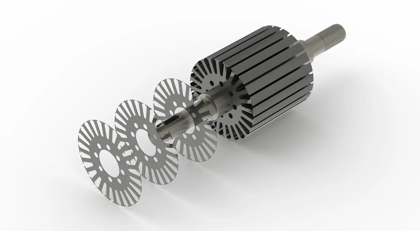
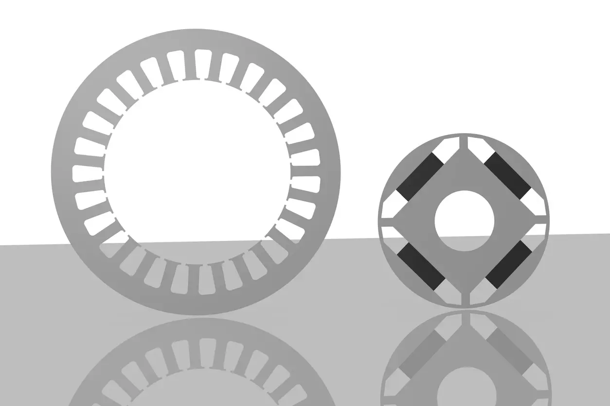
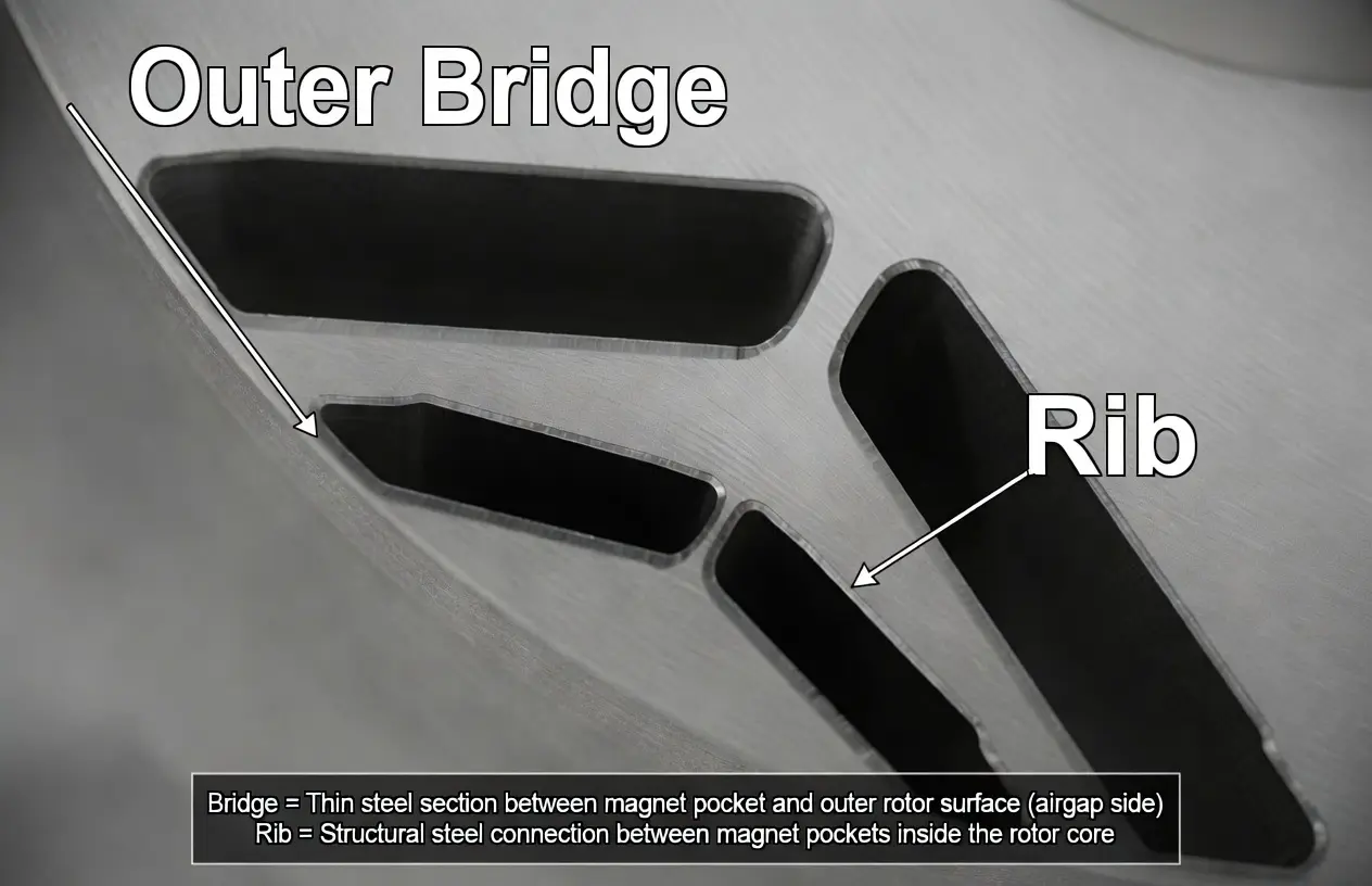
In an IPM machine, the magnets sit inside slots cut into the rotor lamination. Those slots, and the air-filled flux barriers that shape the magnetic circuit, divide the rotor steel into islands. The thin sections of steel left between a slot and the rotor outer surface, and between adjacent barriers, are what hold those islands to the body of the rotor. Engineers call them bridges and ribs.

Terminology varies across the literature, so it is worth fixing the terms used here. A bridge is the thin web of steel at the rotor periphery, on the airgap side of a magnet pocket or flux barrier. A rib (also called a center post) is an internal radial web spanning a barrier deeper inside the rotor. Both serve the same purpose — structural continuity — and both behave the same way magnetically. Some authors use “bridge” for all of these features; this article uses bridge for the outer, airgap-side web and rib for internal supports, and treats the design principles as common to both.
Without bridges and ribs, a segmented IPM rotor lamination would not be a single part. They are what turn a punched sheet full of slots into a rotor that can transmit torque and survive rotation. For the broader context of how these features fit into the machine, see our pillar guide on electric motor rotor design and engineering fundamentals.
| Feature | Location in the lamination | Primary function |
|---|---|---|
| Bridge | Thin web at the rotor periphery, airgap side of a magnet pocket or barrier | Holds the outer rotor steel to the rotor body; resists the centrifugal pull of the magnets |
| Rib / center post | Internal radial web between flux barriers, deeper in the rotor | Adds structural continuity across barriers; shares the centrifugal load |
| Flux barrier | Air-filled slot shaping the magnetic circuit | Directs working flux; not a structural member |
Why Do Rotor Bridges Cause Flux Leakage?
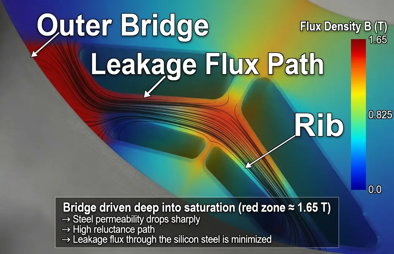
A bridge is a continuous piece of ferromagnetic steel connecting two regions that the magnetic design is trying to keep separate — for example, the two poles around a buried magnet. That continuity gives flux an easy path to circulate locally, around the magnet and back, instead of crossing the airgap into the stator. Flux that takes this short-circuit route is leakage flux: it never links the stator winding, so it produces no torque and no back-EMF.
The design response is to run the bridges in deep magnetic saturation. Steel that is already saturated behaves, for any additional flux, almost like air — its incremental permeability collapses toward that of free space. A saturated bridge therefore caps the leakage it can carry: once the bridge is saturated by the magnet’s own flux, it cannot easily conduct more. This is why a well-designed IPM bridge is deliberately driven past its knee point; an unsaturated bridge would leak far more.
The penalty still scales with bridge cross-section. A wider bridge presents more saturated steel and leaks more flux, which lowers developed torque, reduces the back-EMF (voltage) constant, and degrades power factor. Finite-element studies of IPM rotors put leakage through paths that include the bridges at roughly 5–15% of total magnet flux in representative designs, although the exact figure is strongly dependent on rotor topology, magnet placement, and bridge geometry. The takeaway for design is directional and reliable: narrower bridges leak less.
How Does Centrifugal Stress Limit Bridge Width?
If flux leakage were the only consideration, every bridge would be vanishingly thin. The constraint that prevents that is mechanical. A spinning rotor throws its mass outward, and the magnets plus the outer rim of rotor steel are held in place only by the bridges and ribs. The centrifugal load concentrates in those thin sections, because they are the smallest cross-sections carrying the largest pull.
Centrifugal stress rises steeply with speed and size. The body force on a rotating mass scales as σ ∝ ρ · ω2 · r2, where ρ is material density, ω is angular speed, and r is radius. The square dependence on both speed and radius means high-speed rotors and large-diameter rotors reach the bridge stress limit first — a 20,000 rpm traction rotor and a slow, large-diameter industrial rotor are very different mechanical problems even at the same bridge width.
When peak stress in a bridge reaches the steel’s yield strength, the bridge deforms plastically. In a rotor that means permanent distortion of the airgap, loss of magnet retention, and, beyond yield, fracture. DOE/ORNL analyses of IPM traction rotors treat the onset of plastic deformation as the criterion that sets the machine’s maximum safe operating speed. Sound bridge design keeps the peak von Mises stress below the steel’s yield strength with a safety margin, and evaluates it at the maximum overspeed the rotor must survive, not at rated speed.
The material sets the ceiling. Rotor laminations are non-oriented (NO) electrical steel, and its mechanical strength is what bounds allowable bridge stress. Standard NO motor grades are optimized for low core loss, not strength; high-strength NO grades trade some magnetic performance for substantially higher yield, which is why high-speed rotors often use them.
| Steel category | Yield strength (MPa) | Tensile strength (MPa) | Elongation (%) |
|---|---|---|---|
| Standard NO motor grade (~0.35 mm) | 300–350 (typical range) | 430–480 (typical range) | 20–30 (typical range) |
| High-strength NO rotor grade | ~500–600 (as-rolled) | Higher than standard | Lower than standard |
Typical ranges for standard non-oriented motor grades and for high-strength rotor grades; values are grade- and supplier-dependent and are not specific to a single named grade. Standard-grade ranges are representative of published NO motor-steel datasheets; the high-strength range reflects as-rolled / delivered values from manufacturer datasheets and peer-reviewed studies of high-silicon NO steel for high-speed rotors, and stress-relief annealing lowers yield while improving core loss.
Narrow vs. Wide Rotor Bridge: How Do You Choose?
The two preceding sections define a direct conflict: electromagnetics wants the bridge thin, mechanics wants it thick. Rotor bridge design is the resolution of that conflict, and it comes down to a single governing rule — use the minimum bridge width that survives the maximum overspeed with an adequate safety factor. As narrow as mechanically allowed; no narrower. Where a given design lands on that scale depends on speed, diameter, and the steel grade available.
| Bridge width | Flux leakage | Torque & power factor | Mechanical margin at speed | Typical application |
|---|---|---|---|---|
| Narrow | Low | High | Low — needs high-strength steel and careful FEA | High-speed traction; deep flux-weakening designs |
| Moderate | Moderate | Moderate | Moderate | General traction and variable-speed industrial |
| Wide | High | Reduced | High | Line-frequency; low-speed or large-diameter; cost-driven |
Yucore engineering insight: The rotor bridge is the one feature in the machine where electromagnetic optimization and mechanical survival meet head-on, and the conflict is resolved entirely at lamination geometry. No material or winding change escapes it — the bridge either survives the overspeed or it does not, and it either leaks acceptable flux or it does not. That makes bridge sizing a stamping-geometry decision first and an electromagnetic one second, which is why it belongs in the conversation between the motor designer and the lamination manufacturer, not on either side alone.
Beyond width itself, designers have other levers. The number of bridges, and the choice between an outer bridge and an internal center post, redistribute the load. Generous fillet radii where a bridge meets the rotor body relieve the stress concentration that otherwise peaks at sharp corners — often a larger effect than width alone. And emerging approaches use locally non-magnetic or dual-phase steel in the bridge region, so the bridge keeps its strength but loses its ability to carry leakage flux; these remain specialized, but they point to where high-performance rotor design is heading.
How Is Bridge Width Limited by Manufacturing?
A bridge width that survives the stress analysis still has to be manufacturable, and the achievable minimum depends on how the lamination is cut. The right process tracks production volume as much as geometry, and Yucore’s three methods form a clear progression — from prototype to mass production.
Wire EDM cuts the lamination with an electrically eroding wire instead of a punch, applying no mechanical force to the part, which lets it hold very fine features and tighter dimensional accuracy than stamping — it can blank a bridge narrower than any die. But it is slow and expensive per part, so Yucore recommends it only at the prototyping stage: it is the right tool for the first few cores, in single-digit quantities, before tooling investment is justified.
Simple die stamping is the first true production step. It blanks the lamination in a single station or a compound die, with tooling that costs far less than a progressive die, which makes it viable for genuine low-volume production once a design moves past the handful of prototype cores that EDM is suited to. Here the bridge-width limit becomes mechanical: it is bounded by die clearance and tool robustness, because a web too thin relative to the sheet tears during punching or leaves heavy burrs. A common engineering guideline puts the minimum stampable web at roughly one to one-and-a-half times the material thickness — a toolmaker’s rule of thumb, not a codified standard, and the real limit depends on the die, the grade, and the press.
Progressive die stamping is the destination for a program headed toward mass production. It advances the strip through several stations in one press stroke; the tooling is the most expensive to build, but it delivers the lowest cost per part at scale. The same web-width physics applies as for simple-die stamping, but at volume the challenge shifts to holding that bridge geometry consistently across a long production run — a quality-control discipline as much as a tooling one.
| Process | Typical minimum bridge width | Edge quality | Cost profile | Best-fit volume |
|---|---|---|---|---|
| Wire EDM | Finer than stamping; no punching force | Excellent dimensional accuracy | Minimal tooling; high cost per part | Prototyping only — single-digit quantities |
| Simple die stamping | ~1–1.5 × sheet thickness (engineering guideline) | Burr-sensitive; depends on die clearance | Lower tooling cost than progressive | Low-volume production |
| Progressive die stamping | ~1–1.5 × sheet thickness (engineering guideline) | Burr-sensitive; needs tight die clearance | High tooling cost; lowest cost per part | High-volume / mass production |
Yucore engineering insight: The gap between a steel grade’s datasheet strength and the strength delivered in a finished rotor is almost always process-driven. Edge burrs that bridge adjacent laminations, coating damage, and cut-edge degradation all show up first at the thin bridges, because that is where the lamination is most sensitive. Holding bridge geometry to specification is a stamping-control problem, and we manage it with stack-level performance as the endpoint, not the punched dimension alone.
Burr control matters doubly at the bridges. Excess burr height can make electrical contact across adjacent laminations and short the interlamination insulation, raising eddy-current loss locally — the same mechanism covered in our guide to rotor lamination and laminated rotor core construction. At the bridges, that added loss appears exactly where the steel is already most stressed.
Rotor Bridge Design Standards and Yucore’s Approach
There is no single standard that prescribes a rotor bridge width — it is an outcome of electromagnetic and mechanical design, not a tabulated value. The relevant standards bound the inputs and the verification instead. On the mechanical side, IEC 60034-1 requires a rotor to withstand an overspeed test, commonly 120% of rated speed for general-purpose motors, for two minutes; the exact percentage depends on machine category and the edition of the standard, and the applicable value should be taken from the standard itself. On the material side, ASTM A677 and IEC 60404-8-4 cover non-oriented electrical steel and its test methods, and IEC 60034-30-1 defines the IE efficiency classes that motivate low-leakage rotor design. The U.S. Department of Energy publishes extensive resources on motor efficiency. Underpinning all of it for a manufacturer is IATF 16949:2016 — the automotive quality standard that governs the tolerance control needed to hold bridge geometry consistently across a production run.
At Yucore Technologies, rotor laminations are a core product, and we support the full volume path: wire EDM for prototype cores, simple-die stamping for low-volume production, and progressive-die stamping as a program scales to mass production. We work in non-oriented grades from 35CS250 through high-frequency 20CS1500HF, with high-strength options for high-speed rotors, partnering with customers on the bridge geometry, grade, and tolerance control that turn a stress analysis into a part. Bridge design is where datasheet specifications and real rotor performance meet, and it is exactly the kind of decision our half-century of lamination experience is built to support.
Frequently Asked Questions About Rotor Bridge Design
What is the difference between a rotor bridge and a rib?
A rotor bridge is the thin web of steel at the rotor periphery, on the airgap side of a magnet pocket or flux barrier; a rib (or center post) is an internal radial web deeper in the rotor. Terminology is not fully standardized across the literature, but both features serve the same structural purpose and behave the same way magnetically.
Why are rotor bridges run in magnetic saturation?
Running a bridge in saturation caps the leakage flux it can carry. Once the steel is saturated by the magnet’s flux, its incremental permeability drops toward that of air, so it cannot easily conduct additional leakage flux around the airgap. An unsaturated bridge would leak significantly more.
How thin can a rotor bridge be?
As thin as it can be while keeping peak stress below the steel’s yield strength, with a safety margin, at the rotor’s maximum overspeed. There is no universal minimum — it depends on speed, rotor diameter, the steel grade’s yield strength, and the manufacturing process. Higher speed and larger diameter force wider bridges or stronger steel.
Do wider bridges reduce motor torque?
Yes. A wider bridge carries more leakage flux, which bypasses the airgap and produces no torque. Wider bridges therefore lower developed torque, reduce the back-EMF constant, and degrade power factor — which is why bridges are kept as narrow as mechanical limits allow.
What electrical steel is used when bridge stress is critical?
High-strength non-oriented grades, with yield strength on the order of 500–600 MPa or higher in the as-rolled condition, versus roughly 300–350 MPa for standard NO motor grades. They accept higher core loss than low-loss stator grades in exchange for mechanical margin at the bridges; stress-relief annealing lowers yield while improving core loss, so the delivered condition matters. Suppliers such as JFE (N-CORE / JNE series) offer rotor-oriented high-strength variants, and the exact grade is supplier- and application-dependent.
Can wire EDM cut narrower rotor bridges than die stamping?
Yes. Wire EDM erodes the lamination with no mechanical punching force, so it can hold finer features and tighter accuracy than die stamping and produce a narrower bridge. The catch is cost and speed: it is slow and expensive per part, so it is a prototyping method for single-digit quantities. Low-volume production moves to simple-die stamping and high volume to progressive-die stamping, where the minimum stampable web width usually governs the design.
Why Rotor Bridge Design Matters
The rotor bridge is small, but it sits at the intersection of the two hardest constraints in machine design — making torque and surviving rotation. Every IPM and synchronous reluctance rotor carries them, and in high-speed traction the bridge is often the feature that decides the maximum safe speed. Getting it right is not a materials problem or a winding problem; it is a lamination-geometry problem, solved in the cross-section of a punched sheet. That is why it rewards close collaboration between the motor designer who sets the stress and flux targets and the lamination manufacturer who has to cut the part.