Rotor lamination is the practice of building an electric motor’s rotor core from a stack of thin, electrically insulated sheets of silicon steel rather than a solid block. This breaks induced eddy currents into small, high-resistance loops confined to each sheet — reducing rotor core losses by more than 90% and making the laminated rotor core one of the most important efficiency features in modern motor design.
What Is Rotor Lamination?
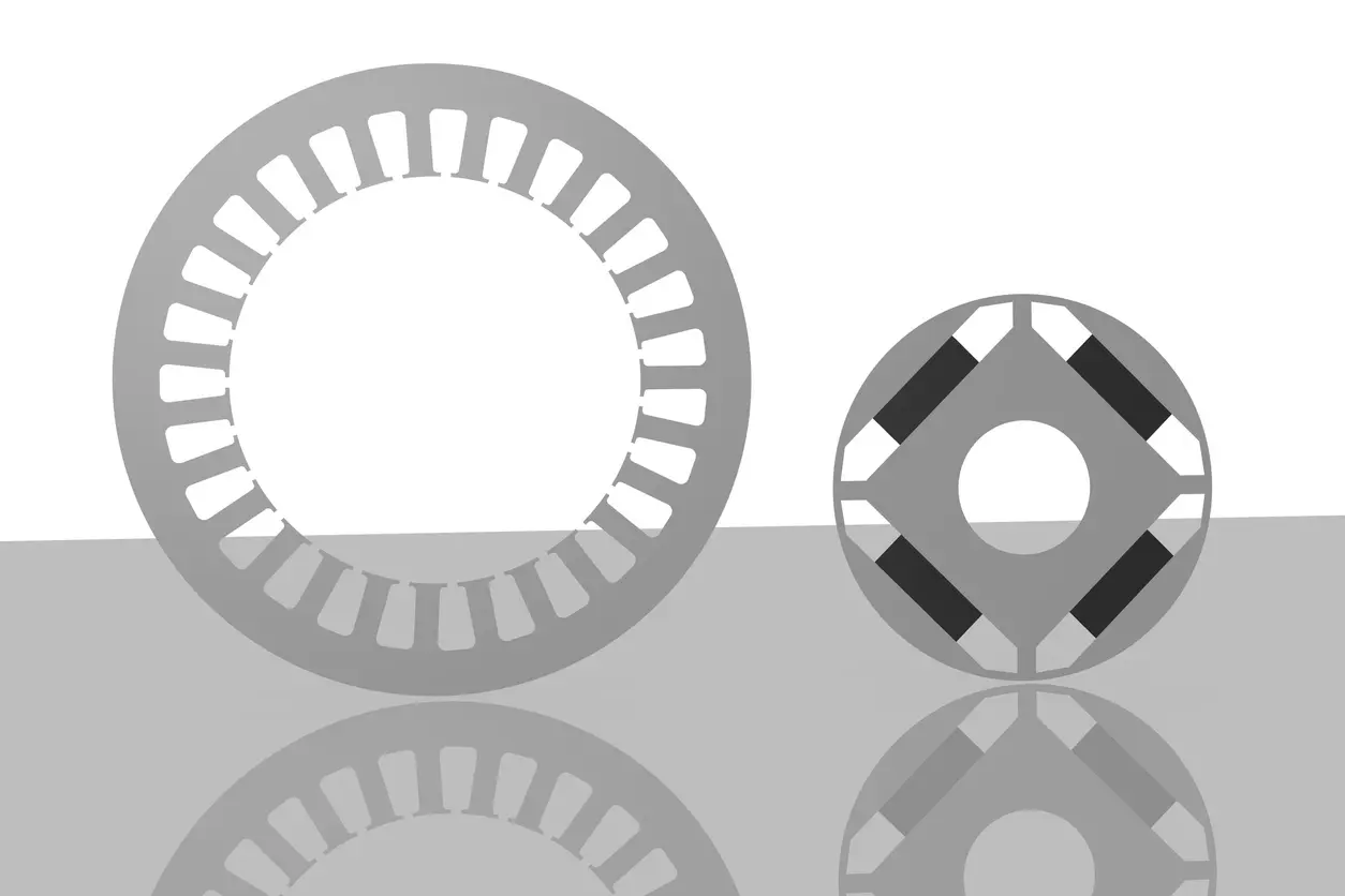
A rotor lamination is a single thin sheet of electrical steel — typically 0.15–0.5 mm thick — stacked axially with hundreds or thousands of others to form the rotor core of an electric motor. Each sheet carries a 0.5–2 μm insulating coating (phosphate-based C-5, organic varnish, or thermosetting adhesive) preventing electrical contact between adjacent laminations.
The laminated rotor core sits at the magnetic center of the machine, carrying flux from permanent magnets, rotor bar currents, or field windings. For how rotor lamination fits into full rotor design, see our pillar article on electric motor rotor design and engineering fundamentals.
Why Laminated Rotor Cores Reduce Eddy Current Losses
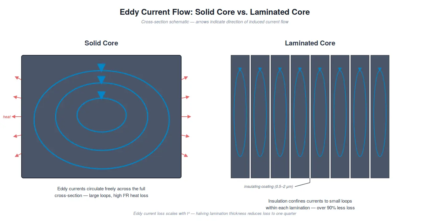
Eddy currents are circulating electrical currents induced in a conductive body whenever it experiences a changing magnetic flux. In a solid rotor, they flow freely across the full cross-section, dissipating energy as heat. Rotor lamination physically constrains that cross-section.
Faraday’s Law and the Eddy Current Loss Equation
By Faraday’s law of induction, a time-varying magnetic field induces an EMF in any conductive material. In an electric motor, the rotor core experiences changing flux from stator field rotation and slot-opening pulsations. The classical eddy current loss in a laminated core is:
Pe = Ke · Bmax2 · f2 · t2 · V / ρ
Where Pe is eddy current power loss, Bmax is peak flux density, f is magnetizing frequency, t is lamination thickness, V is core volume, and ρ is electrical resistivity.
The critical insight for rotor lamination design is the t2 term: loss scales with the square of lamination thickness — halving the thickness reduces eddy current loss to one quarter. The insulating coating between sheets acts as an electrical barrier, confining induced currents to small loops within each lamination rather than letting them circulate across a large rotor cross-section.
Table 1 — Relative Eddy Current Loss vs. Rotor Lamination Thickness
| Lamination Thickness | Relative Eddy Current Loss | Typical Application |
|---|---|---|
| 0.50 mm | 1.00 (baseline) | Line-frequency industrial |
| 0.35 mm | 0.49 | Variable-speed industrial, small motors |
| 0.25 mm | 0.25 | EV traction, medium-frequency drives |
| 0.20 mm | 0.16 | High-performance EV traction |
| 0.10 mm | 0.04 | Ultra-high-speed / high-frequency motors |
Electrical Steel Grades for Rotor Lamination
The overwhelming majority of rotor laminations are stamped from non-oriented (NO) silicon steel — a soft magnetic alloy containing 1%–3.5% silicon. The silicon raises electrical resistivity (directly reducing eddy current loss) and lowers hysteresis loss, at the cost of reduced saturation flux density and increased brittleness.
Common NO grades used in rotor lamination production include M19, 35CS250 for 50/60 Hz industrial motors, and high-frequency grades like 20CS1500HF for traction and variable-speed drives.
Table 2 — NO Electrical Steel Grades for Laminated Rotor Cores
| Grade | Thickness | Core Loss Spec | Typical Application |
|---|---|---|---|
| M19 | 0.35–0.50 mm | W15/50 ≈ 2.2–3.0 W/kg | General-purpose industrial motors |
| 35CS250 | 0.35 mm | W15/50 ≤ 2.50 W/kg | 50/60 Hz industrial, IE2–IE3 motors |
| 35CS210 | 0.35 mm | W15/50 ≤ 2.10 W/kg | High-efficiency motors, IE3–IE4 |
| 20CS1500HF | 0.20 mm | W10/400 ≤ 15.00 W/kg | EV traction, aerospace, high-frequency drives |
Yucore engineering insight: Grade selection for rotor lamination is not frequency-agnostic. Customers starting with M19 or 35CS250 for 50/60 Hz production typically transition to thinner, higher-resistivity grades like 20CS1500HF as applications move toward high-speed EV traction. The right grade is the one matched to the motor’s operating frequency and loss budget — not the most expensive steel available.
Lamination Thickness and Eddy Current Loss
Because eddy current loss scales with the square of lamination thickness, thickness is the single most powerful design lever for reducing rotor core losses. Moving from 0.35 mm rotor lamination to 0.20 mm cuts classical eddy current loss by approximately 67% at the same flux density and frequency.
This physics has driven a clear industry migration. Line-frequency industrial motors still use 0.50 mm or 0.35 mm rotor lamination for cost efficiency, while EV traction manufacturers now specify 0.20–0.25 mm as standard, with next-generation designs exploring 0.10 mm for applications above 20,000 RPM.
Thinner is not universally better: stacking factor decreases as the insulating coating occupies more of the stack height, and manufacturing complexity increases, demanding higher-precision dies and broader manufacturing capabilities.
Table 3 — Rotor Lamination Thickness by Application
| Thickness | Typical Operating Frequency | Typical Application |
|---|---|---|
| 0.50–0.65 mm | 50–60 Hz | Line-frequency industrial motors, generators |
| 0.35 mm | 50–200 Hz | Variable-speed industrial, IE3 motors |
| 0.25 mm | 200–600 Hz | EV traction, premium-efficiency drives |
| 0.20 mm | 400–1,000+ Hz | High-performance EV traction, aerospace |
| 0.10 mm | 1,000+ Hz | Ultra-high-speed motors, specialty applications |
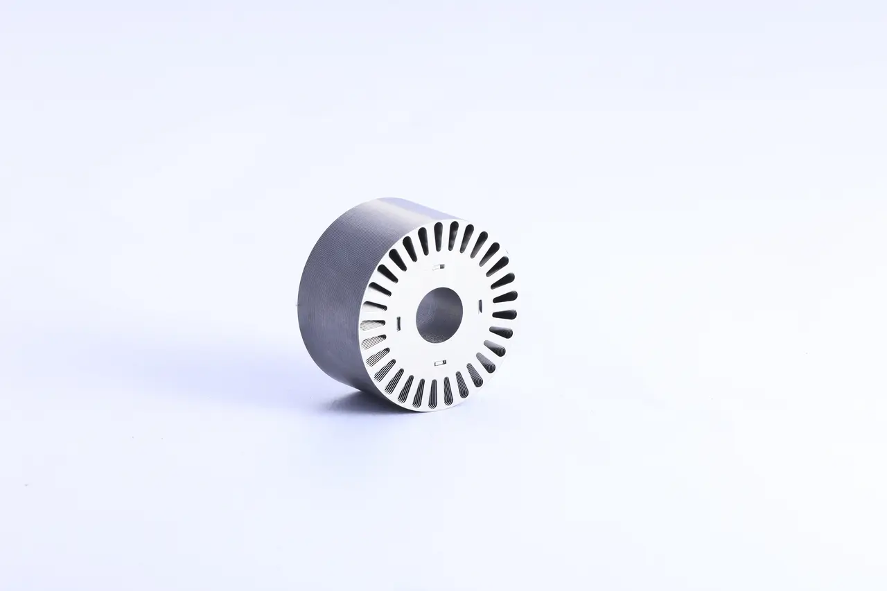
Rotor Lamination Stacking Methods
Once laminations are stamped, they are assembled into a cohesive stack. The rotor lamination stacking method affects rigidity and the interlamination insulation integrity that makes the laminated rotor core work.
Interlocking uses embossed dimples formed during progressive-die stamping; successive laminations self-engage in-press. It is fast, repeatable, and the most common method for high-volume industrial rotor lamination.
Welding applies TIG, laser, or resistance welds in axial seams along the rotor OD. The result is mechanically rigid, but the weld creates a short-circuit path with a minor localized eddy current loss penalty.
Adhesive bonding (self-bonding) uses a thermoset or backlack adhesive applied as part of the interlamination coating, curing into a continuous bonded structure under heat and compression. Self-bonded laminated rotor cores offer the best insulation integrity and are preferred for loss-sensitive high-frequency designs.
Loose stacking relies on end-plate compression alone and is reserved for prototypes or specialty builds.
Table 4 — Rotor Lamination Stacking Methods Compared
| Method | Rigidity | Cost | Insulation Integrity | Typical Use Case |
|---|---|---|---|---|
| Interlocking | Good | Low | Minor disruption at dimples | High-volume industrial |
| Welding | Very high | Medium | Short-circuit at weld line | Large rotors, high-torque machines |
| Adhesive / self-bonding | Very high | High | Best — fully preserved | EV traction, aerospace |
| Loose stacking | Variable | Low | Preserved (if coating intact) | Prototypes, specialty builds |
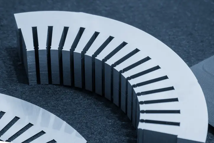
Manufacturing Considerations for Laminated Rotor Cores
Even a correctly specified rotor lamination grade and stacking method can underperform if stamping quality is poor. Die clearance of 5–8% of material thickness per side minimizes edge burrs — the most underappreciated factor in rotor lamination performance, because excessive burrs make electrical contact across adjacent laminations and short the insulation, sharply increasing eddy current loss. Coating integrity demands a continuous film, and stress-relief annealing after stamping restores magnetic properties degraded by cold work.
Yucore engineering insight: The gap between a steel grade’s datasheet performance and its delivered performance in a finished rotor stack is almost always manufacturing-driven. Burr height, coating damage, and interlamination short paths are the three most common reasons a laminated rotor core underperforms its loss target — which is why we specify stamping and handling with stack-level loss performance as the endpoint.
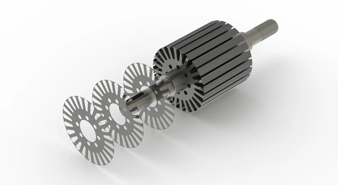
Real-World Impact: Rotor Lamination in EV Traction Motors
Consider a 100 kW permanent-magnet synchronous traction motor operating at roughly 800 Hz at peak speed. At this frequency, the squared frequency dependence of eddy current loss means rotor lamination thickness dramatically impacts total rotor core loss.
Switching from a 0.35 mm laminated rotor core to 0.20 mm rotor lamination cuts classical eddy current loss by approximately 67% at the same flux density. For a rotor generating several hundred watts of core loss at peak, this is a meaningful efficiency gain — and a reduction in rotor thermal load that directly affects magnet demagnetization risk and continuous torque rating. This is why traction motors meeting IE4 and IE5 efficiency classes specify thin, high-frequency NO electrical steel.
Standards and Yucore’s Approach
Specifications for rotor lamination and laminated rotor core construction draw on ASTM A677 (nonoriented electrical steel), IEC 60404-8-4 (NO electrical steel test methods), and IEC 60034-30-1 (motor efficiency classes IE1–IE5). The U.S. Department of Energy publishes extensive resources on industrial motor efficiency.
At Yucore Technologies, rotor lamination is a core product category. Our production focuses on precision-stamped laminated rotor cores in NO grades from 35CS250 through 20CS1500HF for high-frequency EV traction. We work directly with customers on grade selection, stacking method, and tolerance control — bridging datasheet specifications and real-world rotor stack performance.
Frequently Asked Questions About Rotor Lamination
What is the ideal thickness for rotor lamination?
There is no universal ideal — optimal rotor lamination thickness depends on operating frequency and loss budget. Line-frequency industrial motors typically use 0.35–0.50 mm; EV traction motors use 0.20–0.25 mm; ultra-high-speed applications may use 0.10 mm.
Why can’t a rotor core be made from solid steel?
A solid rotor provides a continuous conductive cross-section for induced eddy currents, and the resulting losses can exceed 15–20% of input power in medium-power motors. Rotor lamination breaks these currents into small, high-resistance loops, reducing losses to a fraction of the solid-rotor value.
How does operating frequency affect rotor lamination thickness selection?
Eddy current loss scales with the square of frequency, so high-frequency motors benefit disproportionately from thinner laminations. A motor at 1,000 Hz generates roughly 280 times the per-unit eddy current loss of a 60 Hz motor at the same flux density and thickness — making thin, high-resistivity rotor lamination essential.
Why Rotor Lamination Matters
Rotor lamination is one of the oldest and most effective techniques in electric motor engineering, and it remains central to every modern efficiency class — from industrial motors to cutting-edge EV traction drives. Thin sheets of high-resistivity silicon steel, insulated and stacked with tight tolerances, deliver dramatic eddy current loss reductions that compound across the service life of every motor. For the full engineering picture, see our pillar article on electric motor rotor design and engineering fundamentals.