A skewed rotor offsets laminations by a small angle to spatially average slotting harmonics, cutting cogging torque, torque ripple, and NVH with only modest EMF/efficiency trade-offs.
Key takeaways: start conceptually near one electrical stator-slot pitch, verify with simulation/QC, and reserve “no-skew” only for extreme high-speed or max-torque designs.
1. What is a Skewed Rotor
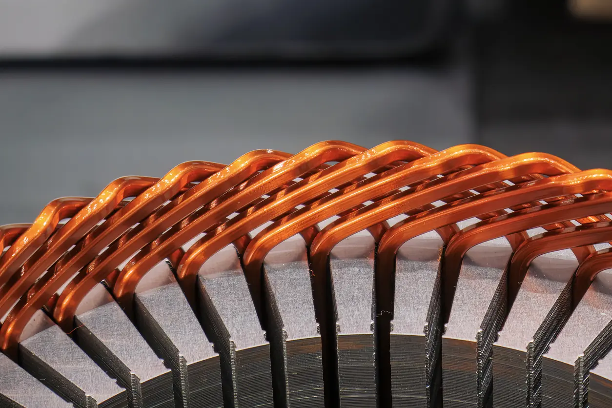
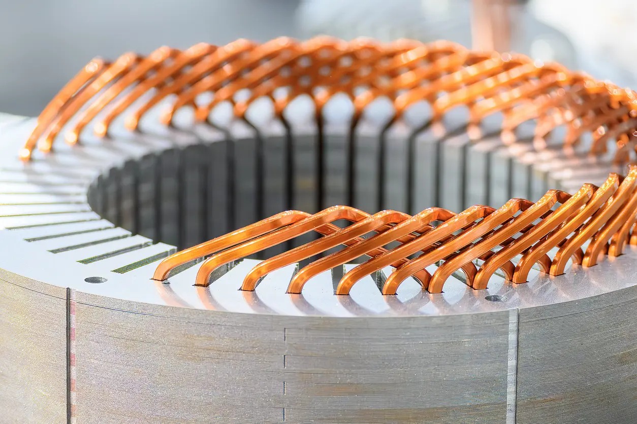
A skewed rotor is a rotor lamination stack built with a deliberate axial twist: each lamination is rotated by a small angle relative to the previous one, typically a fraction of a stator slot pitch. This purposeful misalignment spatially averages slotting effects in the air gap, reducing cogging torque, torque ripple, and audible noise—especially at low speed and light load.
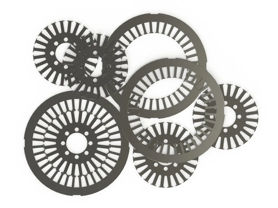
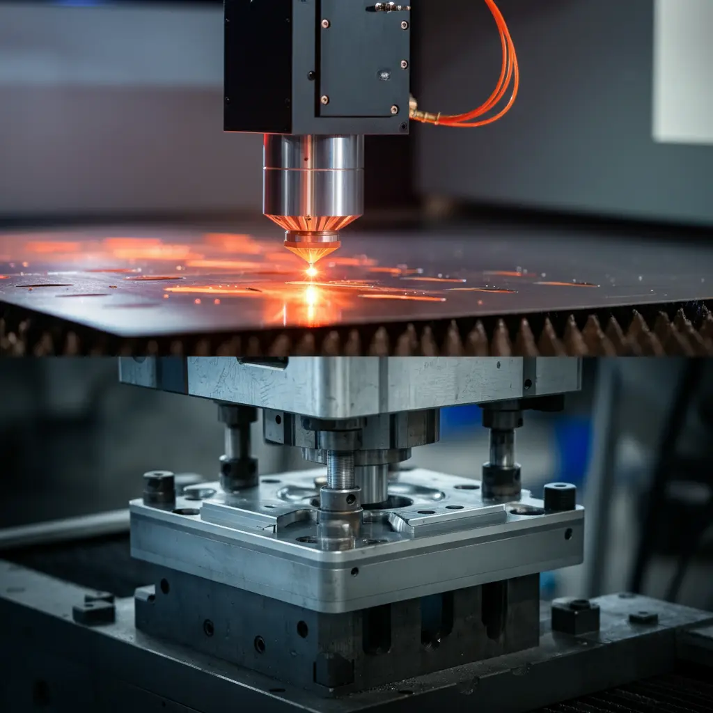
Conceptually, it means the same tooth–slot alignment never repeats along the stack, so local force peaks don’t add up. Implementation is usually step-skew, where precise angular offsets are maintained during stacking—often during the progressive-die stamping stage aided by the interlocking tabs/bonding—to preserve geometry while avoiding distortion, helping a skewed rotor deliver smoother, quieter operation.
2. The Physics: How Skew Averages Slotting Effects
A skewed rotor reshapes the air-gap interaction by spreading slot-related forces along the axial length. Stator teeth create a periodic variation in permeance; when each lamination is rotated by a small angle, those peaks and valleys become phase-shifted from one axial slice to the next. Instead of stacking the same alignment—and the same cogging events—the machine “averages” them.
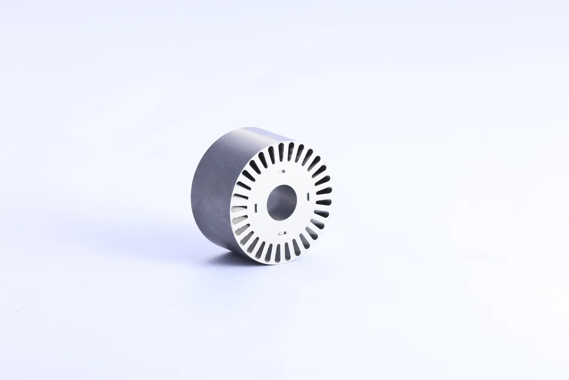
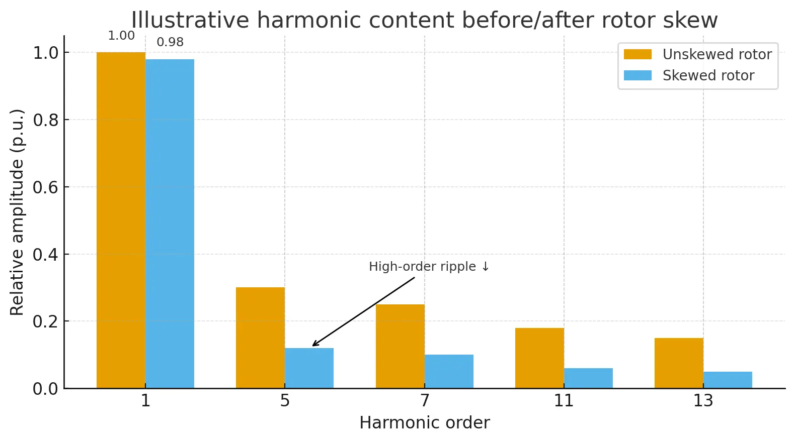
The slotting harmonics that would normally add coherently now cancel partially, because their spatial phases no longer line up perfectly. In torque terms, the Maxwell-stress spikes are diluted, yielding a smoother electromagnetic torque and a cleaner back-EMF waveform. Importantly, the fundamental harmonic component is mostly preserved while higher-order ripple is reduced, which is why designers lean on a skewed rotor for quieter starts and steadier low-speed control.
3. Practical Benefits: Less Ripple, Less Noise
A skewed rotor turns electromagnetic smoothing into practical wins you can feel: quieter operation, steadier torque, and friendlier control tuning. By breaking the perfect axial alignment of slotting forces, skew cuts the peaks that drive cogging and torque ripple, so low-speed crawl, stop-start, and precise positioning feel less “notchy.”
The acoustic payoff is real-world NVH improvement—less tonal whine and fewer resonant triggers across the speed range—making compliance easier for appliances, robots, and industrial machinery etc. Control systems also benefit: cleaner back-EMF and reduced ripple mean smoother current loops, better sensorless observability, and fewer surprises in FOC tuning.
Mechanically, lower excitation of structural modes can translate to less bearing chatter and longer component life. With accurate step-skew and stable bonding, a skewed rotor keeps these gains consistent over time.
4. The Give-and-Take: EMF, Leakage, and Efficiency
A skewed rotor buys smoothness by redistributing the air-gap interaction, and that choice comes with measured trade-offs.
Because skew slightly attenuates the fundamental component, back-EMF (and torque constant) can dip a little, especially as the skew angle approaches a slot pitch.
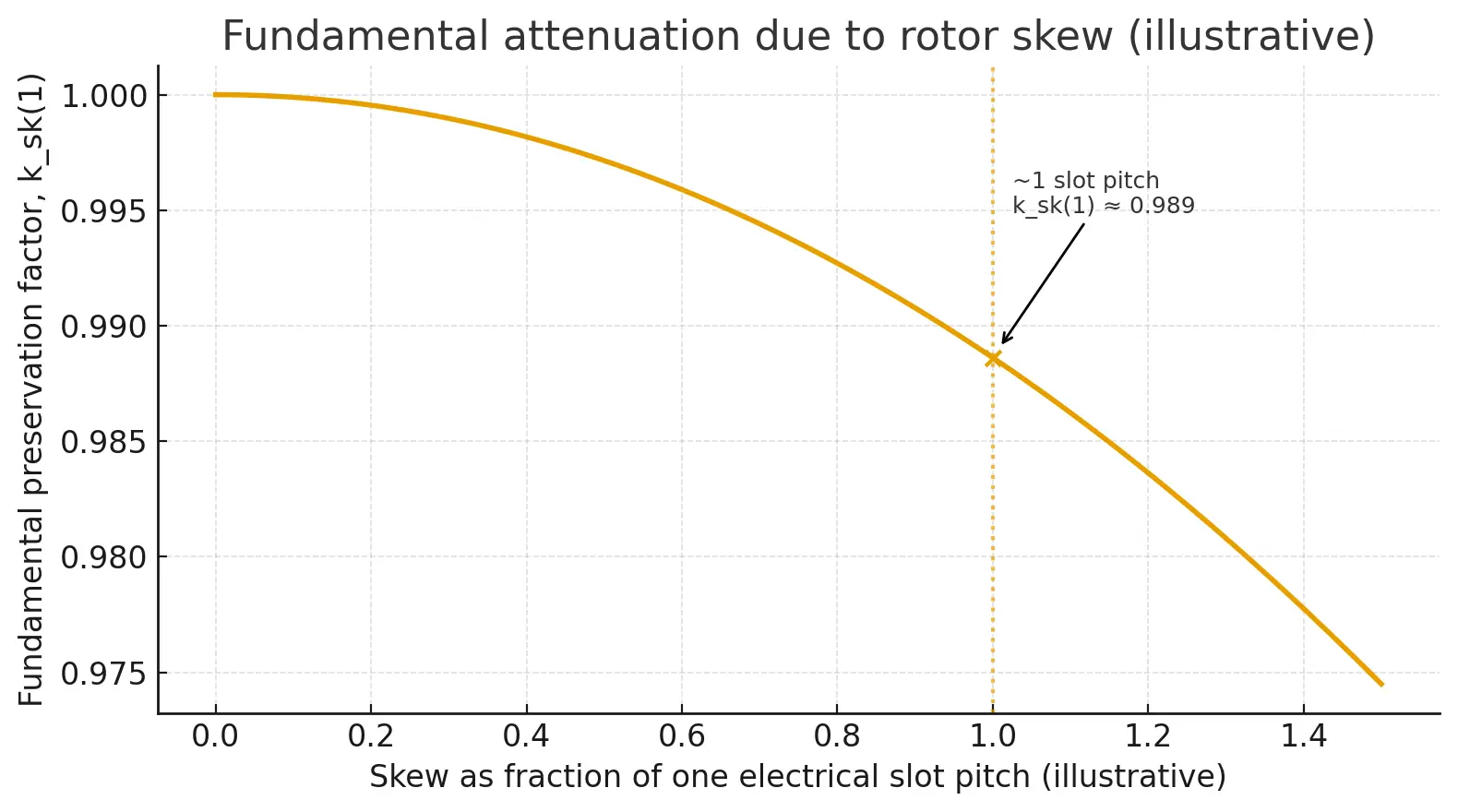
At the same time, flux leakage pathways and effective air gap reactance tend to rise, nudging magnetizing current upward in induction machines and adding a touch of phase lag in PMSMs.
Net efficiency impact is usually modest: you lose a bit from lower EMF and increased leakage, but you also trim core and copper losses tied to high-order harmonics that a skewed rotor suppresses.
In many applications the system wins—cleaner waveforms reduce current ripple, thermal hotspots, and control dithering—so delivered efficiency and NVH compliance improve under real duty cycles.
The takeaway is design balance: pick a skew that knocks down slotting harmonics without overshooting, and ensure tight stacking tolerances so the skewed rotor performs exactly as modeled.
5. Choosing a Skew Angle Conceptually (and When Not to)
A skewed rotor is best chosen by aiming at the dominant slotting harmonic: start near one electrical stator-slot pitch, then tune up or down to balance ripple reduction against fundamental EMF loss. Conceptually, skew works like spatial averaging, so machines with strong slotting effects (tight air gaps, fractional-slot windings) gain the most.
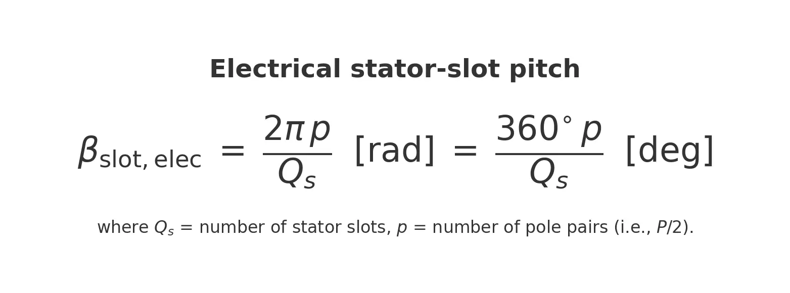
Use simulation or quick sample stacks to compare torque ripple, NVH, and control smoothness versus small EMF/efficiency penalties.
When to be cautious: very high-speed rotors where axial forces and 3D end effects matter, designs chasing maximum torque density for a strong stall(starting) torque, or situations where magnet/bar geometry already mitigates cogging.
Keep manufacturing real—step-skew, burr orientation, and bonding must hold angle precisely—so the skewed rotor you build matches the one you modeled.
Comparison Table — Pros, Cons, and Use Cases
| Use case / machine type | Why a skewed rotor helps (pros) | Trade-offs / watch-outs (cons) | Conceptual starting point |
| PMSM / BLDC with fractional-slot windings | Major cogging reduction; smoother low-speed control; quieter acoustics | Slight fundamental EMF drop; mitigation of axial thrust force/leakage increase | Aim the skew at the dominant slotting harmonic order (often near one stator-slot pitch) |
| Induction motor (squirrel-cage) | Suppresses slot harmonics, crawling/locking; smoother start; lower tonal noise | Small rise in magnetizing current; tiny torque constant reduction | Target the slot-passing content; validate with current spectrum and start tests |
| Precision servo / robotics / cobots | “Notch-free” motion at crawl speeds; easier FOC tuning; better sensorless observability | Peak torque density very slightly reduced | Tune skew to hit ripple without overshooting EMF loss; check bandwidth needs |
| Appliances / HVAC / white goods | NVH compliance; fewer resonant triggers; better user perception | Fractional efficiency penalty in some duty cycles | Prioritize acoustic signature over fractional efficiency |
| Medical devices / lab automation | Smooth force output for positioning; quieter operation | Tight dimensional/QC control required to keep skew true over life | Pair skew with rigorous metrology and stable bonding |
| Linear/transport (elevators, AGVs) | Less tonal hum; gentler ride feel | Slightly lower thrust/torque constant | Use skew as one lever alongside slot/pole pairing and structural damping |
| High-speed spindles, aerospace rotors | Often avoid or minimize skew due to axial forces and 3D end effects | Reduced torque density and possible deformation of the rotor component | Prefer geometry/winding fixes first; use micro-skew only if NVH demands it |
FAQs
1) What problem does a skewed rotor actually solve?
It averages space harmonics from stator slotting so torque ripple and cogging don’t add coherently along the stack.
2) How much skew angle should I use?
Conceptually start near one electrical stator-slot pitch and iterate with FEA/prototypes to balance ripple reduction vs. EMF loss.
3) Does skew rotor always reduce efficiency?
There’s a small trade-off (slight EMF and reactance changes), often offset by lower harmonic copper/core losses under real duty cycles.
4) Is skew only for PMSMs?
No—induction machines benefit too (reduced slot harmonics, smoother starts). Designers also skew magnets (e.g. IPM design) or stator teeth for similar effects.
5) When should I avoid skew?
Very high-speed rotors, designs chasing maximum torque density, or machines already de-cogged by geometry/winding choices.
6) How is skew lamination stack implemented in manufacturing?
Typically step-skew during progressive-die stacking; accuracy relies on die quality, burr orientation, and a stable bonding method.
7) How do I verify the skew I designed is the skew I got?
Use optical/CMM checks of cumulative angle vs. axial position and confirm via harmonic content in back-EMF/torque testing.
8) Does skew affect control?
Yes—cleaner back-EMF reduces current ripple, eases FOC tuning, and improves low-speed sensorless performance.
Author Viewpoint
Personally, I think the electric machinery industry nowadays is underscoring the high efficiency, high conversion rate metrics widely. But given the wide variety of electric motors’ parameters, such as the winding configuration and lamination geometry design, motor designs can vary significantly depending on their unique application areas. Skewing is not the latest innovation but definitely plays an important role for designers seeking low cogging, smoother, and quieter operations. After considering the inevitable engineering trade-offs of skewed rotor stack design, motor designers could find this method very beneficial to application such as medical devices where audible noise and user experience matter as much as torque.

