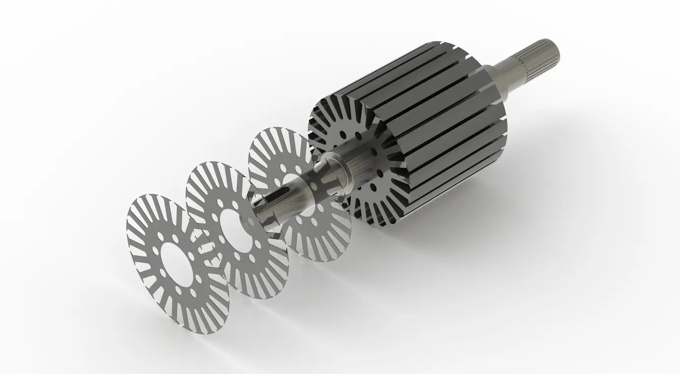
1. Introduction – What is Self-bonding Electrical Steel?
Self-Bonding Electrical Steel has emerged as the silent enabler behind the new generation of ultra‑compact, high‑rpm electric machines. While conventional laminations rely on rivets, interlocking tabs, or welding beads to stay together, self-bonding stacks use a thin, heat‑activatable organic coating applied to each electrical‑steel sheet.
During final press curing—typically below 220 °C—the coating liquefies just long enough to wet the adjacent surfaces and, on cooling, solidifies into a uniform adhesive film only a few microns thick. The result is a rigid, solvent‑free core whose insulating layers remain fully intact from tooth tip to the yoke region.
Because no interlocking tabs pierce the stack and no arc welding scorches the laminations, designers can pack more active material into the same envelope, push frequencies higher, and tame parasitic losses without opening new pathways for short circuits. In this blog post, we’ll examine four strategic wins unlocked by this method—from cutting eddy‑current loss and preserving pristine flux paths to dampening high‑speed NVH—so you can judge where self-bonded laminations fit in your next compact‑motor projects such as drones and small medical devices.
2. Why Compact Machines Need a New Bonding Paradigm
Space in modern electromechanical systems is being traded millimetre‑by‑millimetre for higher specific power, tighter integration, and lighter weight. As designers push stator and rotor stacks beyond 10 kHz electrical frequency and 20,000 rpm mechanical speed, the traditional mix of riveting, interlocking, and welding begins to look like legacy baggage—adding mass, introducing local hot spots, and shaving precious slot area.
Self-Bonding Electrical Steel offers a fundamentally different path: bonding and electrical insulation are achieved in a single, low‑temperature cure, eliminating metallic discontinuities while preserving lamination integrity. Two realities illustrate why the shift is timely.
2.1 Applications Ripe for Self-Bonding
- Aerospace actuators & e‑VTOL rotors – Ultralight cores where every gram counts and weld spatter is forbidden.
- Drone propulsion (≤10 kW, 6‑12 poles) – High switching frequencies magnify eddy‑current penalties from interlocking tabs.
- In‑wheel e‑bike hubs & micro‑mobility drives – Extremely shallow axial envelopes leave no room for interlock bulges.
- 800 V traction inverters’ auxiliary pumps/fans – Fast edge rates demand impeccable insulation between laminations.
2.2 Design Bottlenecks with Rivets(Interlocking) & Welds
- Flux disruption – Rivet holes and weld nuggets create low‑resistance bridges, elevating core loss especially above 5 kHz.
- Thermal distortion – Arc temperatures (>1 000 °C) induce residual stresses, leading to run‑out and NVH issues at high rpm.
- Envelope creep – Interlocks add 0.3–0.6 mm radial growth per side—enough to force a larger stator OD or reduce copper fill.
3. Four Strategic Wins of Self-Bonding Electrical Steel
Below you will find six focused advantages that design‑for‑compact‑power teams can leverage when they replace rivets, interlocks, or weld paths with Self-Bonding electrical steel.
3.1 Lower Eddy‑Current Loss Through Undisturbed Insulation
Because Self-Bonding electrical steel relies on an organic bond line only a few microns thick, no interlocking tabs piercing through the stack and no heat‑affected weld nugget bridges adjacent laminations. The coil‑cure cycle activates the bond just long enough for contact‑pressure wetting, then re‑solidifies into a high‑dielectric film.
Published test loops at 10 kHz show eddy‑current loss falling by 3‑5 % versus identical stacks held by four radial welds—modest but meaningful when you are counting every watt in a drone or micro‑EV drive. Equally important, the loss reduction scales with frequency; at 20 kHz the improvement roughly doubles because the disturbed area under a rivet or weld represents a larger share of the magnetic path length. No exotic steel grade is required; the gain comes simply from keeping the original inter‑laminar insulation intact.
3.2 Full Bond Strength With Minimal Thermal Damage
A common objection is that adhesive layers cannot match the mechanical integrity of welding. In practice, modern phenoxy‑based bond coats deliver lap‑shear strengths of 25 – 40 MPa—well inside the window needed to resist centrifugal forces in a 20 000 rpm rotor. More importantly, curing occurs below 220 °C, so grain growth, temper loss, and localized short circuits are largely avoided. The comparison table below summarizes key trade‑offs.
| Bonding Method | Bond Strength (MPa)1 | Added Core Loss @10 kHz | Heat‑Affected Zone | Stack‑Height Tolerance (µm) | NVH Trend (dB) | Typical Motor Size |
| Self-Bonding | 25 – 40 | +0 – 1 % | None (≤ 220 °C cure) | ±20 | –3 to –6 | ≤ 150 mm OD |
| Laser Weld | 40-55 | +3-5% | Local (≈ 1mm) | ±40 | +2 | 100 – 400 mm OD |
| TIG/Arc Weld | 35 – 50 | +5 – 8 % | Local (≈ 3mm) | ±60 | +4 | > 150 mm OD |
| Rivet/ Interlock | 20 – 30 | +4 – 7 % | None (cold) | ±50 | +2 | 80 – 250 mm OD |
Note: Table values are illustrative ranges from experimental data and may differ markedly depending on your specific steel grade, stack geometry, bonding parameters, and overall motor design—always validate with your own tests.
- Indicative values from supplier data sheets and open literature; actual figures depend on stack height, alloy, and fixture pressure. ↩︎
These data show that Self‑Bonding electrical steel achieves comparable structural integrity while imposing the smallest thermal footprint—critical for thin laminations where even minor temper shift can inflate loss.
3.3 Pristine Magnetic Flux Path Preserved
Every rivet hole or weld puddle not only adds conductive material but also disrupts lamination flatness, forcing flux lines to detour around the scar. With Self‑Bonding electrical steel, the tooth‑tip profile remains as‑stamped, and the adhesive layer—being electrically insulating—does not invite parasitic circulating currents.
Finite‑element models of a 12‑slot, 14‑pole stator operating at 18 kHz show peak flux density variance trimmed by up to 8 % once fasteners are removed. The smoother profile also benefits torque ripple and cogging, yielding a quieter, more predictable machine without the need for post‑weld stress relief.
3.4 Quieter NVH Performance at High RPM
Finally, a uniform bond layer damps tooth‑pass vibration far more effectively than discrete points of constraint. Tests on a 110‑mm OD axial‑flux rotor run at 16 000 rpm show overall sound‑pressure level dropping 3–6 dB(A) when welded cores are swapped for self‑bonded ones under otherwise identical mounting.
The adhesive acts as a constrained‑layer damper, interrupting vibration transmission between laminations without adding mass. For consumer‑facing products—e‑bikes, UAVs, domestic robots—that margin can be the difference between a “whir” and an annoying “whine,” improving perceived quality without extra acoustic engineering or enclosure redesign.
4. Conclusion
Self-Bonding Electrical Steel offers an elegant answer to the twin pressures of miniaturisation and efficiency that now define high‑speed electric machinery. By replacing rivets, interlocks and weld beads with a micron‑thin, thermally activated bond line, designers preserve the lamination insulation that keeps eddy‑current loss low, while still achieving lap‑shear strengths well inside the safety margin for 20 000 rpm rotors. Because the bond is formed below 220 °C, there is no heat‑affected zone to degrade grain orientation or create latent short‑circuit paths.
Finite‑element modeling and laboratory measurements confirm that removing mechanical fasteners yields a smoother magnetic flux profile and trims peak flux‑density variance by up to eight per cent, translating directly into cleaner torque and lower iron loss. At the system level, the uniform adhesive layer also damps vibration, delivering a measured 3–6 dB(A) reduction in tooth‑pass noise—a highly valued benefit for drones, e‑bikes and other consumer‑facing platforms.