Table of Contents
What Are The 2 Core Losses From Stack Lamination Perspective?
One of the two core losses, eddy-current loss arises when a changing magnetic field threads each lamination and induces closed-loop currents inside the steel. By Ohm’s and Joule’s laws, those circulating currents convert electrical energy directly into heat. Their magnitude depends on three geometric factors a manufacturer can influence: lamination thickness, the continuity of surface insulation, and the electrical resistivity of the alloy. Thin, well-insulated sheets interrupt current paths and force charges to take longer, higher-resistance routes, sharply damping this portion of Core Losses, especially at higher switching frequencies.
Hysteresis loss is embedded in the steel’s own magnetic “memory.” Each time the flux reverses, the domains inside every grain must rotate or flip, expending a fixed packet of energy equal to the area of the material’s B-H loop. Any operation that disturbs the lattice—cold-rolling, punching, welding—widens that loop and drives up Core Losses. Gas stress-relief annealing restores the microstructure by letting atoms relax back toward their low-energy positions, shrinking the loop and stabilizing performance over the motor’s entire duty range.
1. Select Premium Electrical Steel Grade
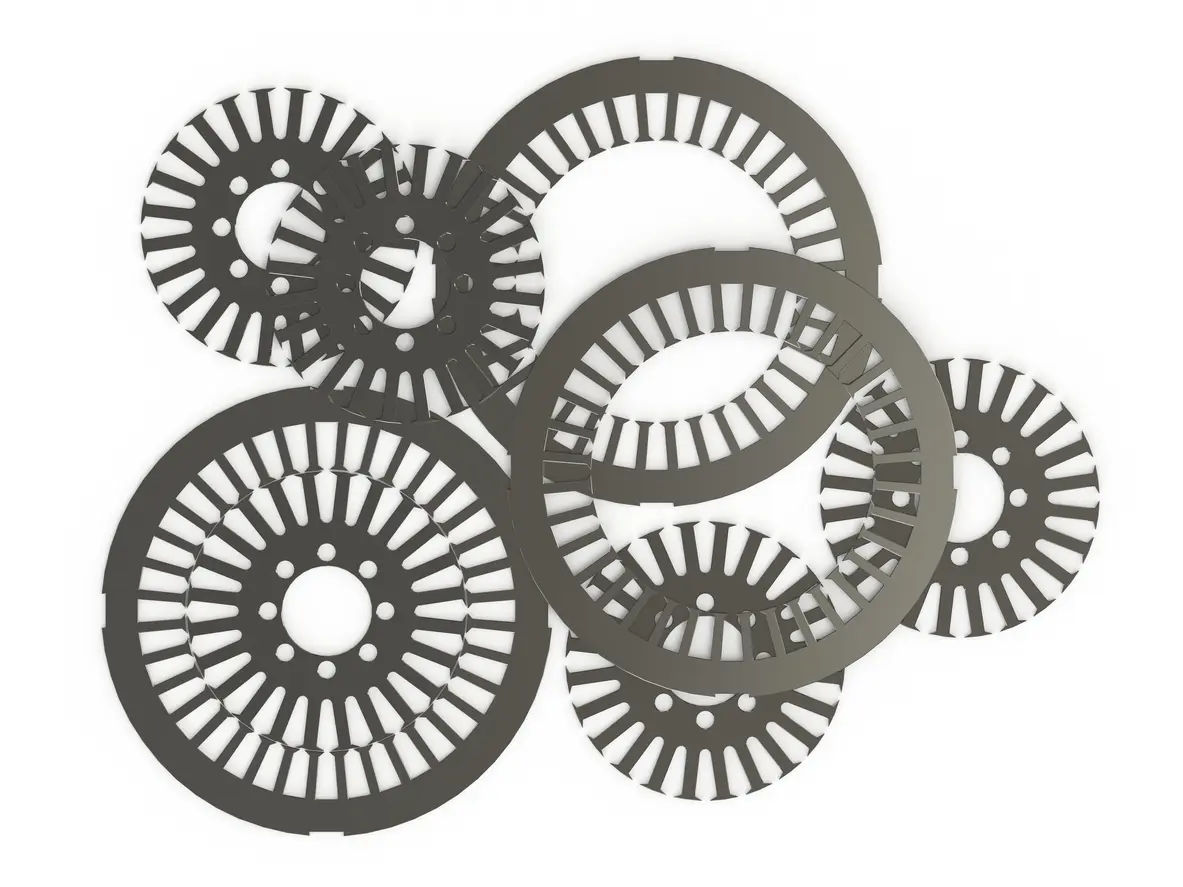
Premium electrical steel starts the fight against core losses at the material level. Higher-grade alloys are rolled to finer, thinner gauges such as 0.2 mm, so each lamination offers a shorter path for induced eddy currents. When the motor’s field reverses, those currents encounter more insulating boundaries and less cross-sectional area, dissipating far less heat than in standard-thickness sheets such as 0.5, 0.65 mm.
Datasheets from any E-steel manufacturers illustrate the classic compromise between magnetic flux density (how much excitation the core can carry) and iron loss (the penalty for using that excitation). On a typical chart, the lower-loss grades sit to the left, while high-saturation grades sit higher up the Y-axis; moving toward one axis usually nudges you away from the other. Designers often pick a middle point, accepting either extra copper turns or additional cooling to balance the motor.
Premium non-oriented silicon steels and emerging Fe-Co blends tilt that graph in both directions at once: they preserve low hysteresis and eddy-current figures while allowing higher usable flux before saturation. In practice, this widens the electromagnetic “safe zone,” letting engineers dial in stronger torque or faster speed without crossing thermal limits—proof that selecting the right steel is the most leverage-rich step toward ultra-low core losses.
2. Reduce Lamination Thickness
Eddy current loss can be approximated by

where B_max is peak flux density, f is electrical frequency, t is lamination thickness, ρ is resistivity, and k gathers geometric factors. Because the thickness term is squared, trimming gauge from 0.35 mm to 0.20 mm can cut the eddy component of Core Losses by more than half without touching the coil or magnet design. Thinner sheets break up the closed loops that swirling currents prefer, forcing those currents to cross additional insulation barriers and lose energy as they go.
If left unchecked, eddy currents add to the total heat budget, raising average winding temperature and nudging insulation toward its thermal class limit. That heat feeds back into higher copper resistance and further efficiency erosion—a cascade no high-performance drive can afford. Reducing thickness not only lowers absolute iron loss but also flattens its rise with frequency, which is critical for inverter-fed motors that experience rich harmonic spectra. The practical payoff is a cooler, lighter stator or rotor that can tolerate higher switching frequencies without drifting beyond its Core Losses ceiling, giving designers headroom for torque or speed gains instead of oversizing the cooling loop.
3. Safeguard Surface Insulation Coatings
Intact inter-laminar insulation is the quiet guardian of ultra-low Core Losses. Modern mills apply inorganic-organic hybrids such as ASTM A976 Type C-5, whose ceramic fillers raise surface resistivity well above that of basic varnishes, blocking most cross-sheet currents even after stress-relief anneal (UPG Enterprises LLC). Yet the benefit lasts only as long as the coating remains unbroken. Burrs from dull punches, over-tight slitting tension, or careless handling can pierce the film and let neighboring laminations behave like one thicker plate, re-creating eddy paths the insulation was meant to stop (newcoreinc.com).
Routine verification is therefore part of manufacturing discipline. The Franklin test—specified in ASTM A717 and widely used on press lines—measures the current that leaks through a small probe under set force and voltage; values drifting upward signal coating fatigue before Core Losses spike in finished stacks (lasertechnologiesinc.com, iTeh Standards). Complement that check with humidity-controlled storage below 50 % RH to keep hygroscopic semi-organic layers from absorbing moisture and losing resistance. Finally, avoid welding or grinding near bare edges; localized heat can carbonize organics and short adjacent sheets. By combining robust coating choice, gentle material flow, and targeted testing, manufacturers keep surface resistivity high and the eddy-current portion of Core Losses comfortably low throughout the motor’s service life.
4. Implement Gas Stress-Relief Annealing
Two gas-fired heat-treatment routes dominate modern lamination shops. Bell-type batch furnaces load complete stator or rotor stacks under a sealed hood, then flood the chamber with a protective 95 % nitrogen / 5 % hydrogen mix. A soak between 700 °C and 820 °C is typical for non-oriented grades, high enough to mobilize dislocations yet safely below the steel’s recrystallization point (ScienceDirect). For high-volume lines, continuous tunnel furnaces convey stamped laminations through sequential heating, hold, and rapid-cool zones while the same H₂–N₂ atmosphere keeps oxidation in check (tenova.com). Both methods may substitute 100 % dry hydrogen when manufacturers need a brighter finish or faster heat transfer.
Why anneal at all? Stamping and shearing concentrate cold-work at the cut edge, expanding the B-H loop and inflating hysteresis-driven Core Losses. A controlled gas atmosphere supplies the thermal energy that allows the distorted crystal lattice to relax; grain boundaries shift, internal stresses fall, and domain walls can again move with less drag. Because the treatment penetrates only a few hundred microns, dimensional accuracy remains intact while edge microstructure returns close to its rolled condition—restoring low Core Losses post-manufactured without altering the motor’s geometry.
5. Opt for Low-Stress Bonding over Welding or Interlocking
Self-bonding begins with a thin adhesive layer deposited on both faces of every electrical-steel sheet at the mill. When a loose stack is clamped and warmed, the pre-coat melts, fills any microscopic voids, and cures into a continuous glassy film that locks the laminations together while preserving their insulation. The process produces a rigid, fully sealed core whose inter-laminar barriers stay intact, so the eddy-current portion of Core Losses remains at its theoretical minimum.
Welding or riveting, by comparison, pierces coatings and introduces localized heat or stress. Each metal bridge can short neighboring sheets and disturb the microstructure surrounding the joint, adding unwanted hysteresis and raising overall Core Losses. Low-stress bonding avoids those problems altogether, distributing mechanical loads uniformly and preventing laminae from fretting against one another. The result is a structurally sound, electrically isolated stack that maintains the pristine magnetic performance achieved in earlier production steps.
Conclusion
Carefully managing Core Losses is a multidisciplinary exercise that begins with the steel coil and ends at the finished stack. Selecting premium electrical steel narrows the hysteresis loop; reducing lamination thickness shortens eddy-current paths; guarding surface coatings keeps adjacent sheets electrically separate; gas stress-relief annealing restores the lattice damaged during cutting; and low-stress bonding maintains insulation while delivering structural integrity. Individually, each step trims a distinct slice of loss, but their real value emerges when they operate in concert. Consistent material quality, precise tooling, clean handling, controlled atmospheres, and adhesive joining together create a virtuous chain in which improvements made early in the line are not undone later.
For designers, lower iron dissipation unlocks higher flux densities, wider frequency ranges, and cooler thermal profiles without resorting to oversized cooling systems or additional copper mass. For manufacturers, the same practices translate into tighter process windows, lower scrap rates, and more predictable performance audits. Ultimately, ultra-low Core Losses are less a single breakthrough than the cumulative effect of disciplined choices at every stage of production—choices that turn the raw potential of electrical steel into the reliable, high-efficiency cores demanded by modern electric-motor applications.

