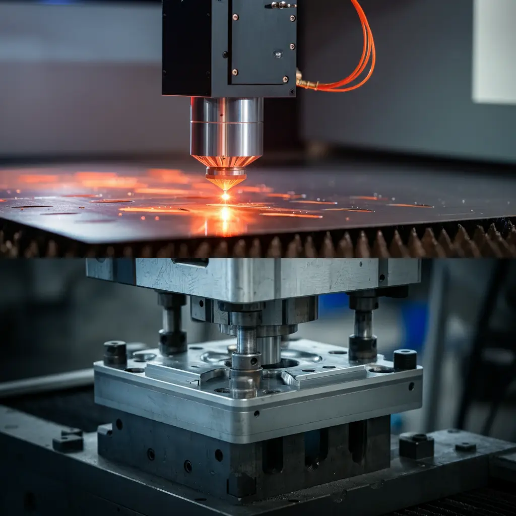
Discover 5 key ways the electric motor core and armature boost performance. Learn about torque generation, motor rotation physics, and optimal material selection for efficiency.
1. Introduction to Electric Motor Cores
1.1 The Crucial Role of the Armature
a. Overview of Electric Motor Components
Electric motors are essential devices that convert electrical energy into mechanical energy, powering a wide array of applications from household appliances to industrial machinery. The primary components of an electric motor include the stator, rotor, and armature.
- Stator: This is the stationary part of the motor that generates a magnetic field. It typically consists of windings or permanent magnets mounted on the motor’s housing. The stator’s magnetic field is crucial for inducing motion in the rotor.
- Rotor: The rotor is the rotating component that turns the motor’s shaft, delivering mechanical power to perform work. It is situated inside the stator and interacts directly with its magnetic field.
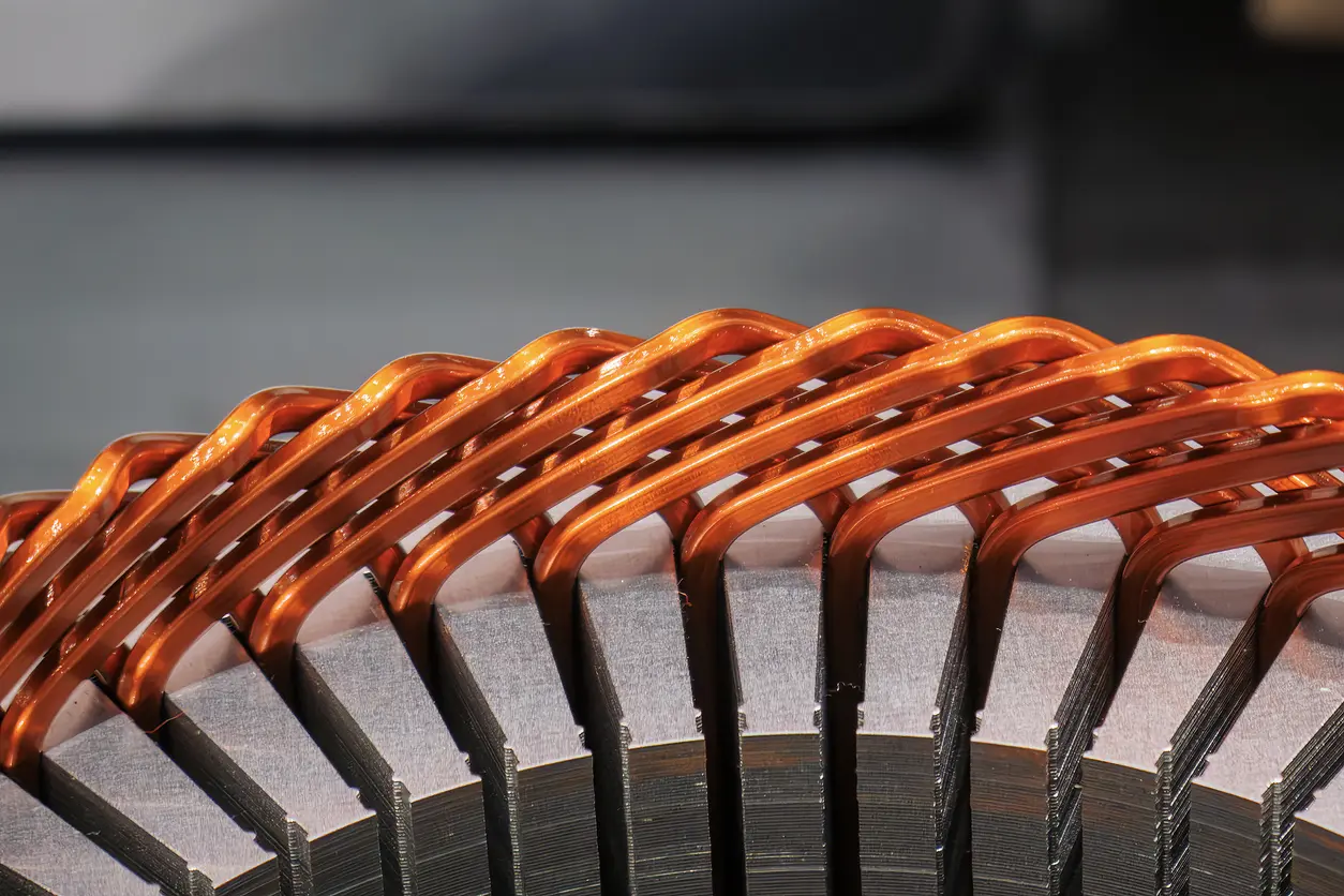
- Armature: Often located on the rotor, the armature is a set of windings or coils through which electric current flows. It is the key element where electricity is converted into mechanical torque. In some motor designs, the terms “rotor” and “armature” are used interchangeably because the armature windings are mounted on the rotor itself.
b. Importance of the Armature in Motor Function
The armature plays a pivotal role in the functioning of an electric motor. It is responsible for carrying the electric current that interacts with the magnetic field generated by the stator. This interaction is the cornerstone of the motor’s ability to produce rotational torque.
When direct current (DC) flows through the armature windings, it creates its own magnetic field. According to Lorentz’s Law, when a current-carrying conductor is placed within a magnetic field, it experiences a force perpendicular to both the direction of the magnetic field and the current. This force generates torque on the armature, causing it to rotate.
The rotation of the armature is transmitted to the motor’s shaft, producing mechanical work. The efficiency and performance of the motor heavily depend on the design and material of the armature. High-quality materials with excellent magnetic properties are used to minimize energy losses due to eddy currents and hysteresis, enhancing the motor’s overall efficiency.
Understanding the armature’s function is essential for optimizing motor design. By improving the armature’s efficiency, manufacturers can develop motors that are more powerful, energy-efficient, and reliable.
For a more in-depth exploration of electric motor components and their functions, you may refer to educational resources provided by reputable institutions like IEEE or detailed engineering textbooks on electric machinery.
2. How DC Current Creates Rotational Torque
2.1 The Physics Behind Motor Rotation
a. Electromagnetic Principles
Electric motors operate on fundamental electromagnetic principles to convert electrical energy into mechanical motion. When direct current (DC) flows through the armature windings of a motor, it generates magnetic fields around the conductors due to the movement of electrons. These magnetic fields interact with the magnetic field produced by the stator, which consists of permanent magnets or electromagnets.
In the armature, the windings are arranged so that the magnetic fields they produce reinforce each other, creating a strong overall magnetic field with distinct north and south poles. The interaction between the magnetic fields of the armature (rotor) and the stator results in forces acting on the armature conductors.
This interplay is governed by Ampère’s Law and Faraday’s Law of Electromagnetic Induction, which describe how electric currents produce magnetic fields and how changing magnetic fields can induce electric currents, respectively. However, in a DC motor, the primary focus is on the magnetic fields produced by steady currents and their interactions.
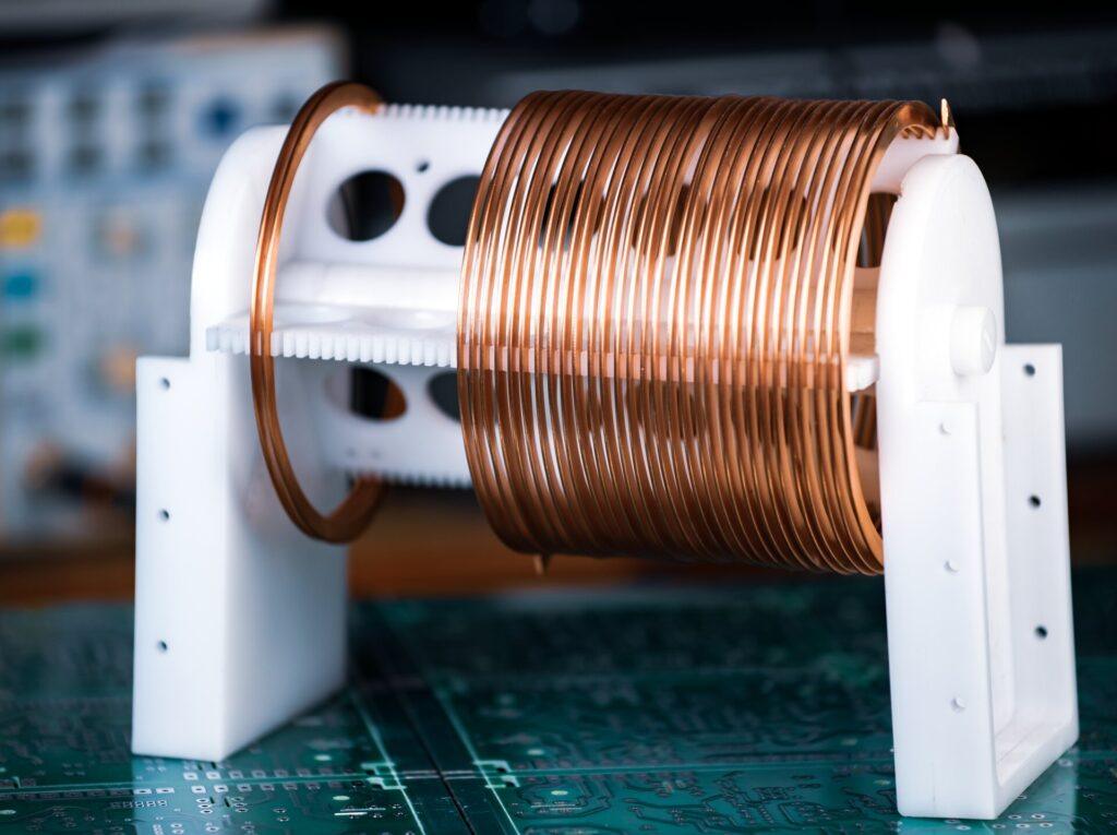
b. Lorentz Force and Torque Generation
The rotational motion in electric motors is primarily due to the Lorentz force, which states that a current-carrying conductor within a magnetic field experiences a force. The mathematical expression for the Lorentz force F is:
F = I(L × B)
Where:
- I is the current through the conductor.
- L is the length vector of the conductor segment.
- B is the magnetic flux density vector.
- × denotes the cross product, indicating that the force is perpendicular to both the current direction and the magnetic field.
In the motor’s armature, multiple conductors are positioned around the core. When DC flows through these windings, each conductor experiences a Lorentz force. Because the conductors are arranged radially, these forces combine to produce a net torque that causes the armature to rotate.
The direction of the torque—and thus the motor’s rotation—is determined by the right-hand rule. If you point your right thumb in the direction of the current and your fingers in the direction of the magnetic field, your palm faces the direction of the force experienced by the conductor.
To maintain continuous rotation, a component called the commutator reverses the current’s direction in the armature windings every half rotation. This reversal ensures that the torque generated by the Lorentz force always acts in the same rotational direction, preventing the motor from oscillating back and forth instead of spinning continuously.
The magnitude of the torque τ produced can be calculated using:
τ = kΦI
Where:
- k is a constant related to the motor’s construction.
- Φ is the magnetic flux per pole.
- I is the current through the armature windings.
Understanding these electromagnetic principles is essential for optimizing motor performance. By adjusting factors such as the strength of the magnetic fields (through material selection and design) and the amount of current supplied, engineers can influence the torque output, efficiency, and speed of the motor.
3. Interaction Between Stator and Rotor
3.1 Magnetic Field Generation
a. Role of the Stator
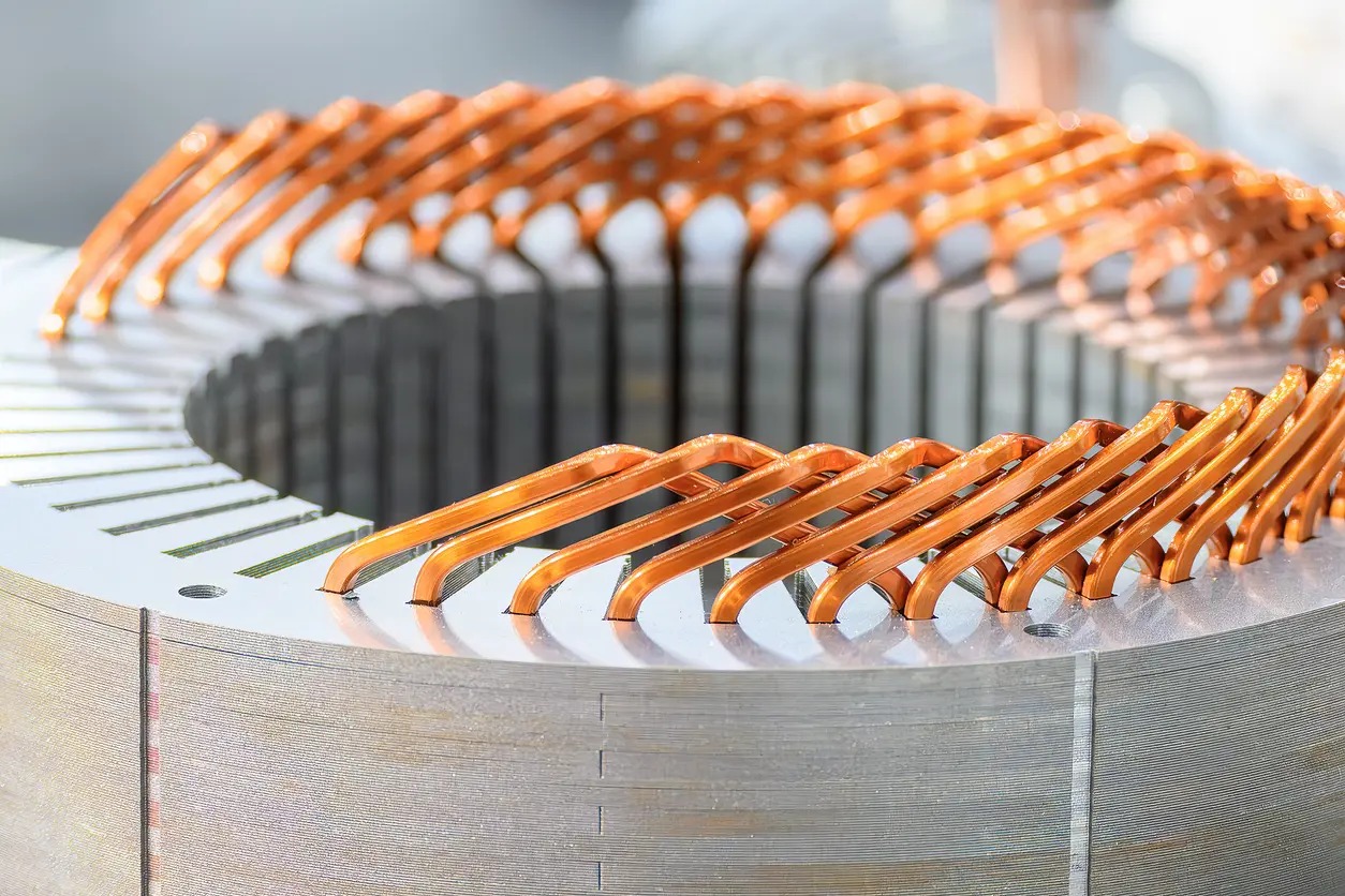
The stator is the stationary part of an electric motor and is fundamental in creating the magnetic field necessary for motor operation. It typically consists of a core made from laminated iron or steel sheets, which helps reduce eddy current losses, and is wound with coils of insulated wire. When electric current flows through these windings, the stator generates a steady magnetic field.
In a DC motor, the stator can use either permanent magnets or electromagnetic windings to produce this magnetic field. The design and configuration of the stator windings are crucial because they determine the strength and distribution of the magnetic field within the motor. A well-designed stator ensures that the magnetic field is uniform and strong, which is essential for efficient motor performance.
The stator’s magnetic field establishes the environment in which the rotor operates. By providing a constant magnetic field, the stator enables the rotor to experience continuous torque as it rotates. The materials used in the stator, such as high-grade electrical steel, are selected to maximize magnetic permeability and minimize energy losses.
b. Function of the Rotor
The rotor is the rotating component of the motor and is situated within the magnetic field produced by the stator. It typically comprises a shaft, a core made of laminated iron or steel, and windings or conductive bars. In many DC motors, the rotor contains the armature windings through which current flows.
When electric current passes through the rotor’s windings, it creates its own magnetic field. This magnetic field interacts with the stator’s magnetic field, resulting in a force on the rotor according to the Lorentz force principle. The combined effect of these forces produces torque, causing the rotor to turn and perform mechanical work.
The rotor’s design is optimized to enhance its interaction with the stator’s magnetic field. This includes arranging the windings or conductive bars to maximize torque and minimize energy losses due to factors like resistance and inductance. The rotor is also balanced mechanically to ensure smooth rotation and reduce wear on bearings and other components.
The continuous interaction between the stator and rotor magnetic fields is what drives the motor’s operation. As the rotor turns, the commutator (in DC motors) or electronic controllers (in AC motors) ensure that the current direction in the rotor windings is appropriately managed to maintain consistent torque and rotational motion. Understanding the relationship between the stator and rotor is essential for optimizing motor performance. Advances in materials and design techniques have led to motors that are more efficient, powerful, and compact.
4. Material Selection for Optimal Performance
4.1 Importance of Core Materials
a. Electrical Steel and Laminations
Selecting the right materials for the electric motor core, particularly the armature, is crucial for achieving optimal performance and efficiency. One of the most commonly used materials in motor cores is electrical steel, also known as silicon steel. This specialized steel contains a small percentage of silicon (typically around 3%), which enhances its magnetic properties and electrical resistivity.
Electrical steel is favored because of its high magnetic permeability, which allows it to efficiently conduct magnetic flux. This property is essential for minimizing energy losses during the magnetization and demagnetization cycles that occur as the motor operates. The material’s low hysteresis loss means that less energy is wasted as heat, improving the overall efficiency of the motor.
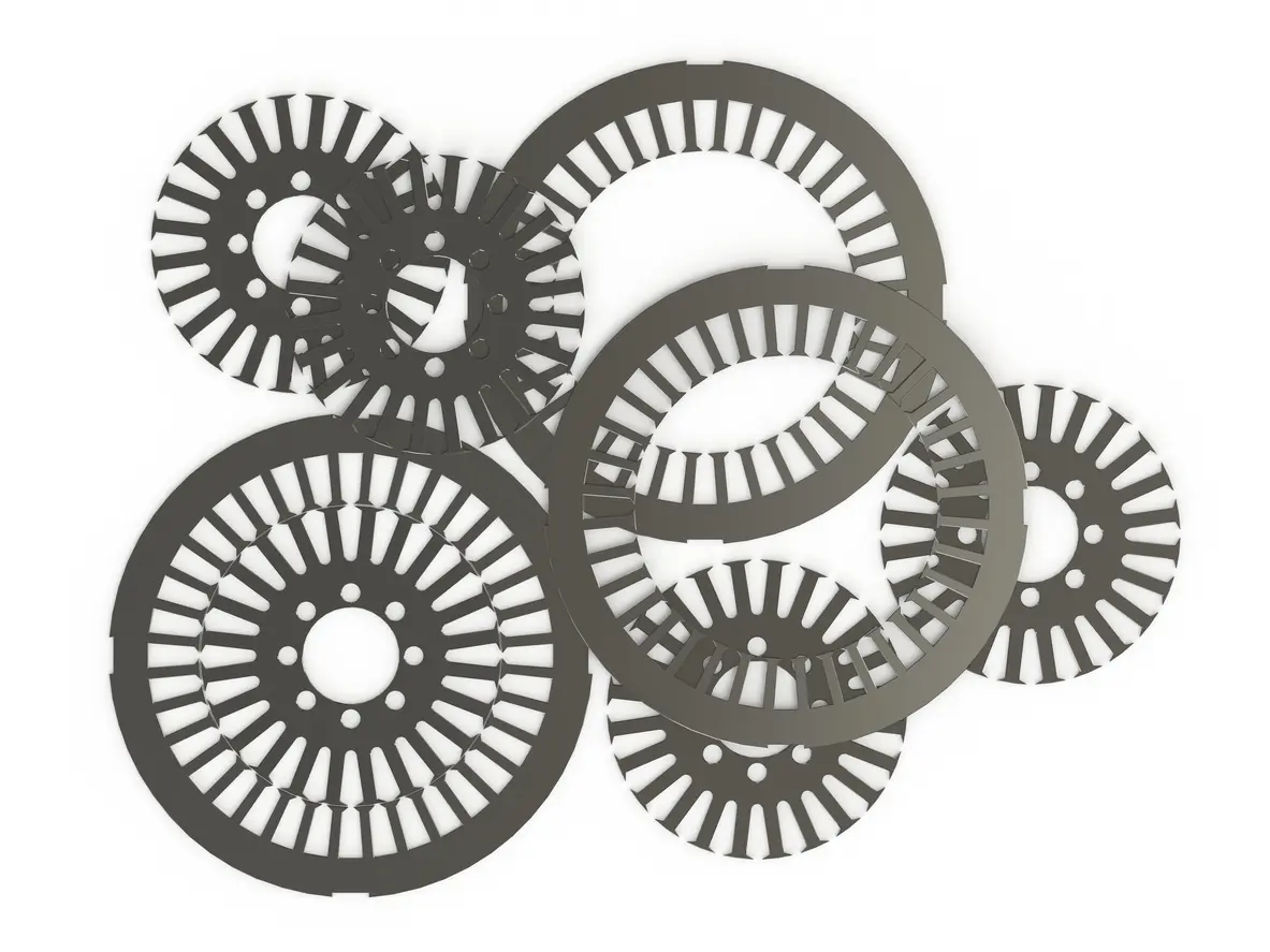
The armature core is constructed from thin sheets or laminations of electrical steel stacked together. The laminated structure is vital for reducing eddy current losses within the core material.
b. Reducing Eddy Current Losses
Eddy currents are loops of electrical current induced within conductors by a changing magnetic field, as described by Faraday’s Law of Electromagnetic Induction. In solid core materials, these currents can become significant, leading to energy losses in the form of heat, which reduces the motor’s efficiency and can cause overheating.
By using thin, insulated laminations of electrical steel in the armature core, the path available for eddy currents is greatly restricted. Each lamination acts as a barrier to the flow of these currents, effectively breaking up larger eddy currents into smaller ones that generate less heat. This design significantly minimizes energy losses and enhances the motor’s performance.
The choice of electrical steel with higher silicon content also contributes to reducing eddy current losses. Increased silicon content raises the electrical resistivity of the steel, further impeding the formation of eddy currents. However, a balance must be struck because too much silicon can make the steel brittle and difficult to work with during manufacturing.
Advancements in material science have led to the development of specialized alloys and treatments that improve the magnetic properties of electrical steel. These innovations allow for thinner laminations and even lower energy losses. For example, grain-oriented electrical steel is engineered to have superior magnetic properties in a specific direction, which can be advantageous in certain motor or generator designs.
Understanding the importance of material selection and core construction is essential for engineers aiming to optimize motor efficiency. By carefully choosing materials and employing techniques like lamination, manufacturers can produce electric motors that are more powerful, efficient, and reliable.
For a deeper understanding of how material selection impacts motor performance and methods to reduce eddy current losses, you might find resources from the International Journal of Engineering Research & Technology helpful, as they provide detailed analyses and research findings on these topics.
References
- International Journal of Engineering Research & Technology (IJERT). (n.d.). Retrieved from https://www.ijert.org/
- Institute of Electrical and Electronics Engineers (IEEE). (n.d.). IEEE Xplore Digital Library. Retrieved from https://ieeexplore.ieee.org/

